QUICK STA E3 and E3 Plus Solid-State Overload Relay Quick Start Guide (Bulletins 193 and 592)
ATTENTION ! This guide does not replace the User Manual, publication 193-UM002_-EN-P, and is intended for qualified service personnel responsible for setting up and servicing these devices. You must have previous experience with and a basic understanding of electrical terminology, configuration procedures, required equipment, and safety precautions. The user manual can be downloaded from http:// literature.rockwellautomation.com.
General Precautions In addition to the specific precautions listed throughout this manual, the following general statements must be observed. IMPORTANT IMPORTANT IMPORTANT IMPORTANT The purpose of this publication is to serve as a guide for proper installation. The National Electrical Code and any other governing regional or local code overrules the information in this publication.A hazard of personal injury/equipment damage exists if codes are ignored during installation.
Introduction Follow these steps to successfully commission the E3 Overload Relay: Table 1: Commissioning Procedure Step Description 1 Hardware Installation 2 Wiring Installation – Typical Motor Connections – External Current Transformer Applications (193-EC_ZZ or 592-EC_ZZ) – External Ground Fault Sensor Applications (193-EC3_ _ , 592-EC3_ _ and 193-EC5_ _ , 592-EC5_ _) 3 DeviceNet Commissioning 4 Setup Requirements Setup for Bulletin 193 or 592-EC1/EC2/EC3/EC5 Overload Relay – Protective Trip
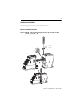
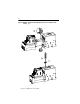
Hardware Installation The following figures illustrate the starter assembly instructions. Starter Assembly Instructions Figure 1: 100-C09…C43 Starter Assembly Instructions (for use with Cat. Nos. 193-EC_ _B and -EC_ _D) 2 /tN 22 lb-in.
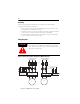
Figure 2: 100-C60…C85 Starter Assembly Instructions (for use with Cat. No. 193-EC_ _E). 1 2 /tN 35 lb-in.
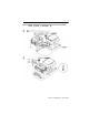
Figure 3: 100-D95...D860 Starter Assembly Instructions (for use with Cat. Nos. 193-EC_ _F, 193-EC_ _G, and 193-EC_ _H).
Wiring Installation Typical Motor Connections Refer to the product nameplate or user manual for power lug termination information including: • Terminal wire size and torque specifications • Maximum wire lengths • Lug kit catalog numbers (108…1250 A) For reliable input signal processing, input wiring should be routed in raceways separate from power cabling.
Control Terminals The following table defines the E3 Overload Relay control terminal designations.
Grounding The following grounding recommendations are provided to ensure electromagnetic compatibility compliance during installation: • The earth ground terminal of the E3 Overload Relay shall be connected to a solid earth ground via a low-impedance connection • Installations employing an external ground fault sensor shall ground the cable shield at the sensor with no connection made at the E3 Plus Overload Relay • The PTC thermistor cable shield shall be grounded at the E3 Plus Overload Relay with no
IMPORTANT IMPORTANT Parameter 27, Single/Three Ph, should be set to single-phase for single-phase devices and three-phase for three-phase devices. In single-phase devices, traditional single-phase wiring (connecting T2 to L3) will result in a vector imbalance of current flowing through the E3 Plus Overload Relay. This will result in inaccurate ground fault reporting and protection. External Current Transformer Application (Cat. No. 193-EC_ZZ) E3 and E3 Plus Overload Relays (Cat. No.
Installation Instructions Cat. No. 193-EC_ZZ Overload Relays are designed to be installed in cat. no. 193-ECPM2 panel mount adapters and connected to separately mounted current transformers. For a panel mount adapter assembly, refer to the instructions included with the panel mount adapter. The E3 Overload Relay must be mounted a distance equal to, or greater than, six times the cable diameter (including insulation) from the nearest current-carrying conductor or current transformer.
Figure 7: External CT Connection Diagrams IEC L1 L2 NEMA L3 L1 L2 L3 K1 L L1/1 L2/3 L3/5 E3 Primary Current Transformers T1/2 T2/4 T3/6 T L1/1 L2/3 L3/5 E3 Primary Current Transformers T1/2 T2/4 T3/6 T1 M T2 T3 M External Potential (Voltage) Transformer Application (Cat. No. 193/592-EC5_ _) The E3 Plus Overload Relay Catalog Number 193/592-EC5_ _ can be used with external step-down potential transformers (PTs).
Figure 8: External PT Connection Diagrams Line L1 L2 L3 N/GND L1 L2 L3 Wye Connection with PTs Load Line L1 L2 L3 L1 L2 L3 L2 L3 Delta Connection with PTs Load Line L1 L2 L3 L1 Open Delta Connection with PTs Load Publication 193-QR003B-EN-P - October 2009
External Ground Fault Sensor Application (Cat. Nos. 193/592-EC3_ _, 193/592-EC4_ _, and 193/592-EC5_ _) Cat. Nos. 193/592-EC3_ _, 193/592-EC4_ _, and 193/592-EC5_ _ E3 Plus Overload Relays are intended to provide ground fault protection when used with the cat. no. 193-CBCT_ external ground fault (core balance) sensor. The ground fault sensor mounts separately from the E3 Plus Overload Relay and must be placed within three meters of the relay.
Figure 10: Ground Fault Sensor Mounting Placement GF Sensor 90˚ Power Cables 6x 6x Figure 11: Power Cable Configuration — Two Cables per Phase L3 1 L2 L1 1 L1 The spacer is a short (approximately 10 times the cable diameter in length) piece of cable with no connections to any terminal.
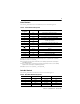
DeviceNet Node Commissioning Overview E3 Overload Relays are shipped with a default software node address (MAC ID) setting of 63 and the data rate set to Autobaud. Each device on a DeviceNet network must have a unique node address which can be set to a value from 0…63. Keep in mind, most DeviceNet systems use address 0 for the master device (scanner) and node address 63 should be left vacant for introduction of new slave devices.
Figure 13: Node Address Switches Table 2: Node Address Setting Switch Settings Description 0…63 The node address setting is determined by the switch values when set in this range. 64…99 For switch settings in this range, the node address setting is determined by the software setting using the RSNetWorx for DeviceNet configuration tool. 99 Factory default setting. Note: For node address switch values in the range of 0…63, cycle power to the E3 Overload Relay to initialize the new setting.
Protective Trip/Warning Summaries & Parameter Group Listing (Cat. Nos. 193/592-EC1/EC2/EC3/EC5) Table 3: Trip Summary Trip Function Overload Trip Enable Factory Default Trip Level Settings Trip Delay Settings Inhibit Time Settings ➊ Range Default Range Default Range Default ➋ ➋ Trip Class 5…30 Trip Class 10 — — Enabled Phase Loss Enabled ➌ ➌ 0.1…25.0 s 1.0 s 0…250 s 0s Ground Fault (193/592-EC2) Disabled Internal 1…5 A 2.5 A 0.0…25.0 s 0.
Table 3: Trip Summary Trip Function Trip Enable Factory Default Trip Level Settings Range Default Trip Delay Settings Range Default Inhibit Time Settings ➊ Range Default Under Consumed kVAR ➐ Disabled 0…32767 0.1…25.0 s 1.0 s 0…250 s 10 s Over Consumed kVAR ➐ Disabled 0…32767 0.1…25.0 s 1.0 s 0…250 s 10 s Under Generated kVAR ➐ Disabled -32767…0 0.1…25.0 s 1.0 s 0…250 s 10 s Over Generated kVAR ➐ Disabled -32767…0 0.1…25.0 s 1.
Table 4: Warning Summary Warning Function Warning Enable Factory Default Warning Level Settings Inhibit Time Settings ➊ Range Default Range Default Disabled 0…100%➋ 85% — — — — — — — Ground Fault (193/592-EC2) Disabled Internal 1…5 A 2.0 A 0…250 s 10 s Ground Fault (193/592-EC3) Disabled External 0.02…5 A ➌ 2.
Table 5: Parameter Group Listing Monitor Params Overload Setup Reset/Lock Advanced Setup DeviceNet Setup Output Setup DeviceLogix 65 OutA Pr FltState 79 Comm Override 1 L1 Current 27 Single/ Three Ph 26 Trip Reset 24 Trip Enable 55 AutoBaudEnable 2 L2 Current 28 FLA Setting 53 Program Lock 25 Warning Enable 56 NonVol Baud Rate 66 OutA Pr FltValue 80 Network Override 81 Net outputs 82 Net Out COS Mask 3 L3 Current 29 Trip Class 54 Set to Defaults 27 Single/Three Ph 58 COS Mask 6
Table 6: Parameter Group Listing, Continued Device Logix 79 Comm Override 80 Network Override 81 Net outputs 82 Net Out COS Mask TripWarn History ➋ Trip Snapshot ➋ Voltage Monitor ➌ Power Monitor Voltage Setup ➌ ➌ Power Setup ➌ 132 Trip History 0 144 SS L1 Current 160 V Trip Status 156 Volt Mode 173 L1 Real Power 157 Power Scale 133 Trip History 1 134 Trip History 2 145 SS L2 Current 146 SS L3 Current 161 V Warn Status 162 L1-L2 Voltage 158 V Trip Enable 159 V Warn Enable 174 L2 Real P
Setup for Cat. No. 193-EC4 Current Monitor Relay After the E3 Plus Current Monitor Relay is installed according to the guidelines specified in this manual, apply power to the relay’s DeviceNet connector. After applying power, the following sequence should occur: 1. The Trip relay should close 2.35 seconds later and the TRIP/WARN LED will not flash (unless a Non-Volatile Fault previously existed or a fault condition is present). 2.
Protective Trip/Warning Summaries & Parameter Group Listing (Cat. No. 193-EC4) Table 7: Trip Summary Trip Function Trip Enable Factory Default Trip Level Settings Trip Delay Settings Inhibit Time Settings Range Default Range Default Range Ground Fault Disabled 0.02…5 A 2.5 A 0.0…25 s 0.5 s 0…250 s 10 s L1 Undercurrent Disabled 0.2…45 A — 0.1…25 s 1.0 s 0…250 s 1.0 s L2 Undercurrent Disabled 0.2…45 A — 0.1…25 s 1.0 s 0…250 s 1.0 s L3 Undercurrent Disabled 0.
Table 8: Warning Summary Warning Function Warning Enable Factory Default Range Default Range Default Range Ground Fault Disabled 0.02…5 A 2.0 A 0.0…25 s 0.0 s 0…250 s 10 s L1 Undercurrent Disabled 0.2…45 A — — — 0…250 s 1.0 s L2 Undercurrent Disabled 0.2…45 A — — — 0…250 s 1.0 s L3 Undercurrent Disabled 0.2…45 A — — — 0…250 s 1.0 s L1 Overcurrent Disabled 0.4…270 A — — — 0…250 s 1.0 s L2 Overcurrent Disabled 0.4…270 A — — — 0…250 s 1.
Table 9: Parameter Group Listing (Cat. No.
Table 10: Parameter Group Listing (Cat. No. 193-EC4), Continued TripWarn History ➊ Trip Snapshot ➊ 132 Trip History 0 144 SS L1 Current 133 Trip History 1 145 SS L2 Current 134 Trip History 2 146 SS L3 Current 135 Trip History 3 148 SS GF Current 136 Trip History 4 137 Warn History 0 138 Warn History 1 139 Warn History 2 140 Warn History 3 141 Warn History 4 142 TripHistory Mask 143 WarnHistory Mask ➊ Series C (FRN 5.
Table 11: Standard Fault Short-Circuit Ratings per UL 508 and CSA 22.2, No. 14 Cat. No. Max. Available Fault Current [A] 193-EC_B, 592EC_T 5000 193-EC_D, 592EC_C 5000 193-EC_E, 592EC_D 10000 193-EC_F 10000 193-EC_G 18000 193-EC_H 42000 193-EC_Z 5000 Max.
Table 12: High Fault Short-Circuit Ratings per UL 508 and CSA 22.2, No. 14 with Bulletin 100-C and 100-D contactors Cat. No. Contactor Max. Available Max. Fault Current Voltage [A] [V] Max.
Table 13: High Fault Short-Circuit Ratings per UL 508 and CSA 22.2, No. 14 with NEMA contactors Cat. No. Contactor Size _T 00 Max. Available Max. Fault Current Voltage [A] [V] 100000 _C 0 _C 1 100000 100000 592-EC1 592-EC2 592-EC3 592-EC5 J 600 — 20 — 240 30 30 FDB 3025/ LFB3070R 30 FDB 3025/ LFB3070R 480 _D 3 100000 100000 30 600 30 240 60 480 240 2 Circuit Breaker/ Limiter R 600 _C Max.
Fuse Coordination Table 15: IEC Type 1 and Type II Fuse Coordination with Bulletin 100-C and 100-D Contactors per EN60947-4-1 Cat. No. Contactor Max. Starter FLC [A] 100-C09 9 100-C12 12 100-C16 16 100-C23 23 40 40 100-C30 30 50 50 100-C37 37 50 50 100-C43 43 70 70 100-C60 60 80 80 100-C72 72 100 100 100-C85 85 150 150 FF, ZZ 100-D95 95 FF, ZZ 100-D110 110 _B _D _E 193-EC1 193-EC2 193-EC3 193-EC4 193-EC5 Prospective Conditional Max.
Table 16: Type 1 and Type II Fuse Coordination with NEMA Contactors Cat. No. Contactor Max. Size Starter FLC [A] Prospective Short-Circuit Current Ir [A] Conditional Short-Circuit Current Iq [A] Max.
Publication 193-QR003B-EN-P - October 2009 PN-37176 Supercedes publication 193-QR003A-EN-P - January 2008 Copyright ©2009 Rockwell Automation, Inc. All Rights Reserved.