
Owner manual

9
Chapter
Troubleshooting and Fault Information
9-1
CHAPTER OBJECTIVES
This chapter provides information about:
LED diagnostics
General troubleshooting procedures
SMP-3 fault information
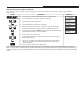
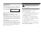
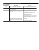
LED DIAGNOSTICS
The SMP-3 overload relay contains four status LEDs that are
intended to aid in troubleshooting and performing fault
diagnostics on the SMP-3 overload relay.
Power This green LED, when illuminated, indicates
that power is applied to terminals 50 and 60.
AC Out A This yellow LED, when illuminated, indicates
that output terminal 10 is energized.
AC Out B This yellow LED, when illuminated, indicates
that output terminal 20 is energized.
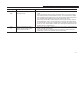
Trip This red trip LED, when illuminated, indicates
that the SMP-3 overload relay is faulted. When
a fault occurs this LED will flash a specific
code that corresponds to a specific fault condi-
tion. The code consists of a specific number of
flashes and then a pause. This code will contin-
ue to be displayed on the trip LED until the
fault is cleared. (See Table 9.A for flash code
information.)
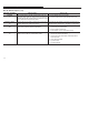
ATTENTION: The yellow OUT A and OUT B
LEDs only indicate that the micro-controller
attempted to turn the output On/Off and is not an
indication that the output did in fact turn On/Off.
ATTENTION: To avoid electric shock hazard or
damage to the equipment only qualified personnel
should perform the following procedures