
Owner manual

Chapter 6 –Serial Communication
6-6
SAMPLE PROGRAM LISTING FOR REMOTE I/O TO SERIAL PORT COMMUNICATION
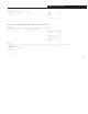
The diagram shown below reflects the memory configuration used in the sample ladder logic program shown in the remaining
portion of this chapter.
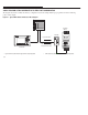
Figure 6.1 Typical SMP-3 R/IO Communication Block Diagram
Logic Control Data
SMP-3 Status Data
Analog Parameter Value
PLC-5
PanelView
Gateway
➀
➁
Contactor
SMP-3
➀Logic Control Data ( Table 6.B) from logic controller’s output image table.➁SMP-3 Status Data (Table 6.C) to logic controller’s input image table.