
Owner manual


Chapter 6 –Serial Communication
6-2
Logic Control Data
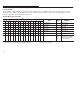
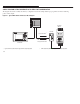
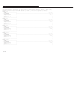
The information in Table 6.B illustrates the logic control data that is sent to the SMP-3 overload relay through the logic controller
output image table. When using the Bulletin 1203-GD1 communication module, this information is sent to the SMP-3 overload
relay when SW3 dip 2 on the 1203-GD1 module is ON.
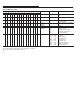
Table 6.B SMP-3 Logic Control Data
Bit
tat
ett
xp a at
15 14 13 12 11 10 9 8 7 6 5 4 3 2 1 0
S
tat
us S
ett
ing E
xp
l
a
n
at
ion
X Turn Out A off 1 Turn Out A off
X Turn Out B off 1 Turn Out B off
X Clear Fault 1 Clear Fault
X Turn Out A on 1 Turn Out A on
X Turn Out B on 1 Turn Out B on
X X X X X X X X Not Used X XXX
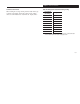
X X X Analog Parameter Selection
➀
001
010
011
100
Average Current
Thermal Capacity Utilized
Full Load Current Setting
Current Unbalance
➀ These three bits are used to specify/request the analog reference parameter the
SMP-3 overload relay should send back with the SMP-3 Status Data.
Note: The Turn Triac Off, Turn Triac On, and Clear Fault
signals are edge sensitive.