
Owner manual
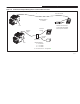


Chapter 3 –Installation and Wiring
3-36
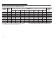
Table 3.I FLC DIP Switch Designations and Minimum Settings
Catalog
er ➊
Current
Range
LC
FLC Switch
Designations
Minimum
Setting
A pere
Numb
er
➊
(F
LC
Range)
SW1 SW2 SW3 SW4 SW5 SW6 SW7 SW8
(
A
m
pere
s)
➋ ➌
xxx–C1Dx (0.7–2.5A) 1.00 0.70 0.40 0.20 0.10 .05 .03 .02 0.70
xxx–C1Fx (2–10A) 5.0 2.0 1.0 1.0 0.5 0.2 0.2 0.1 2.0
xxx–C1Hx (8–37A) 15.0 10.0 5.0 4.0 2.0 1.0 0.5 0.2 8.0
xxx–C1Kx (20–75A) 30 20 10 5 5 2 2 1 20
xxx–C1Lx (20–90A) 40 25 10 5 5 2 2 1 20
xxx–C1Mx (40–180A) 75 50 25 10 10 5 3 2 40
xxx–C1Nx (70–304A) 150 75 40 20 10 5 2 2 70
xxx–C1Px (100–414A) 200 100 50 25 20 10 5 4 100
xxx–C1Rx (140–608A) 300 150 80 40 20 10 5 3 140
➊ The X indicates a variable character in the Catalog Number.
➋ If theSMP-3 FLC is set below the minimum allowable setting shown, the SMP-3
overload relay will fault on a Min FLC SET fault, fault code #6.
➌ If the FLC setting is set below the minimum allowable setting, the SMP-3 overload
relay will default to using and reporting the minimum FLC setting shown in Table 3I.