
Owner manual

Chapter 3 –Installation and Wiring
3-30
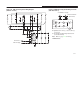
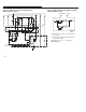
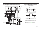
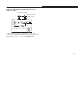
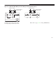
Figure 3.30 Remote Reset Wiring Diagram
Bulletin 800T–NX131
(Back View)
Bulletin 1202 Cable
L1 (+) L2 (–)
P2
P1
P1 (Black Wire)
P2 (Brown Wire)
L
Contact A
(NO)
Jumper A Jumper B
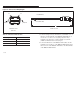
Table 3.H Remote Reset Cable Selections
Catalog Number
“L” Dimension
1202–RRC1 1 Meter (3.28 Ft.)
1202–RRC3 3 Meters (9.84 Ft.)
1202–RRC6 6 Meters (19.69 Ft.)
1. Connect a jumper wire (A) from the L1(+) terminal to one of
the N.O. contact terminals on the Bulletin 800T–NX131, as
shown above. Connect a second jumper (B) from L2(–)
terminal to the other N.O. contact terminal. Use .50 mm
(AWG 22) minimum wire for the jumpers.
2. Connect the black wire of the Bulletin 1202 cable to the P1
terminals as shown above on the Bulletin 800T–NX1311 and
the brown wire of the Bulletin 1202 cable to the P2 terminals
of the Bulletin 800T–NX131.