
Owner manual

Chapter 3 –Installation and Wiring
3-21
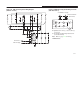
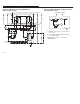
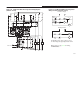
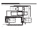
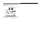
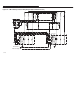
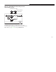
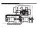
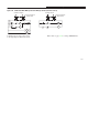
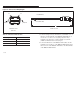
Figure 3.18 SMP-3 Reversing Starter Wiring Diagram Figure 3.19 SMP-3 Reversing Starter Wiring Schematic
(with Triac Control) (with Triac Control)
OUT A
OUT B
FOR
SMP-3
10
20
30
40
50
60
FUSE
TRIP
RELAY
120/240V
AC P/S
T1 T2
T3
L1 L2 L3
REV
To 120V AC or
240V AC Supply
4030
FOR
SMP-3
50 60
OUT A
SMP-3
10
Control Circuit Fuses
(When Used)
To
1
2
0
/24
0
V
AC
S
u
pply
SMP-3
REV
OUT B
SMP-3
20
REV
FOR
➊ Applicable to Cat. No. 193-C1_1, 2,3,4,and 5, 592-C1_T,
A, C, D, and E.
➋ The coil voltage and supply voltage must be the same.
(i.e.120V AC or 240V AC).
Note:Refer to page 3-17 for wiring
ATTENTIONS.