PLEASE READ! This manual is intended to guide qualified personnel in the installation and operation of this product. Because of the variety of uses for this equipment and because of the differences between this solid-state equipment and electromechanical equipment, the user of and those responsible for applying this equipment must satisfy themselves as to the acceptability of each application and use of the equipment.
Table of Contents Chapter 1 – Introduction Chapter Objectives . . . . . . . . . . . . . . . . . . . . . . . . . . . . . . 1-1 Manual Overview . . . . . . . . . . . . . . . . . . . . . . . . . . . . . . . 1-1 Manual Conventions . . . . . . . . . . . . . . . . . . . . . . . . . . . . 1-2 Catalog Number Code Explanation . . . . . . . . . . . . . . . . . 1-2 SMP-3 Overview . . . . . . . . . . . . . . . . . . . . . . . . . . . . . . . 1-3 Functionality . . . . . . . . . . . . . . . . . . . . . . . . .
Table of Contents Phase Loss Protection . . . . . . . . . . . . . . . . . . . . . . . . Ground Fault Protection . . . . . . . . . . . . . . . . . . . . . . Jam/Stall Protection . . . . . . . . . . . . . . . . . . . . . . . . . . 4-6 4-6 4-7 HIM Installation and Removal . . . . . . . . . . . . . . . . . . . . . Installation . . . . . . . . . . . . . . . . . . . . . . . . . . . . . . . . . Removal . . . . . . . . . . . . . . . . . . . . . . . . . . . . . . . . . . . SMP-3 Miscellaneous Features . . . . .
Chapter 9 – Troubleshooting and Fault Information Chapter Objectives . . . . . . . . . . . . . . . . . . . . . . . . . . . . . . 9-1 LED Diagnostics . . . . . . . . . . . . . . . . . . . . . . . . . . . . . . . 9-1 General Troubleshooting Procedures . . . . . . . . . . . . . . . . 9-2 Fault Information . . . . . . . . . . . . . . . . . . . . . . . . . . . . . . . HIM Display. . . . . . . . . . . . . . . . . . . . . . . . . . . . . . . . HIM Fault LED. . . . . . . . . . . . . . . . . . . . . . . . . .
Chapter Introduction CHAPTER OBJECTIVES This chapter provides an overview of this manual and briefly describes the SMP-3 overload relay, highlighting the available features and benefits. MANUAL OVERVIEW The purpose of this manual is to provide the user with the necessary information to install, program, start up and maintain the SMP-3 overload relay. To help ensure successful installation and operation, the material presented in this manual must be thoroughly read and understood before proceeding.
Chapter 1 – Introduction MANUAL CONVENTIONS To help differentiate parameter names and display text from other text in this manual, the following conventions will be used: Parameter Names appear in bold. Display Text appear in ‘‘quotes”. CATALOG NUMBER CODE EXPLANATION 193 – 592 Bulletin Number Any reference to SMP-3 HIM refers to Bulletin 193–HIM1. C1 D SMP-3➊ D F H K L M N P R 193 193 193 193 0.7 – 2.5 2.
Chapter 1 – Introduction SMP-3 OVERVIEW – Automatic or manual reset (1 DIP) The SMP-3 overload relay is a solid-state electronic overload relay that is separately powered and microprocessor-based.
Chapter 1 – Introduction Status – OUT A ON/OFF The SMP-3 overload relay can communicate the specified status and control data to and from the following Human Interface and Communication Modules: – OUT B ON/OFF – Fault code – Protection parameter values: Parameter #1: Average Current Parameter #2: FLC Setting Parameter #3: Thermal Capacity Used Parameter #4: Current Unbalance – Additional parameter values (displayed on HIM only) Parameter #5: SMP-3 Firmware Revision Parameter #6: Device Port # Parameter
Chapter Before Installation 2 CHAPTER OBJECTIVES INSPECTING This chapter describes the instructions regarding receiving, unpacking, inspecting, and storing your SMP-3 overload relay. For optimum performance of your SMP-3 relay, follow these instructions thoroughly. After unpacking, check the item(s) nameplate catalog number against the purchase order. An explanation of the catalog numbering system for the SMP-3 overload relay is included as an aid for the nameplate interpretation.
Chapter 2 – Before Installation GENERAL PRECAUTIONS In addition to the specific precautions listed throughout this manual, the following general statements must be observed. ATTENTION: The SMP-3 overload relay contains ESD– (electrostatic discharge) sensitive parts and assemblies. Static control precautions are required when installing, testing, servicing, or repairing this assembly. Component damage may result if ESD control procedures are not followed.
Installation and Wiring CHAPTER OBJECTIVES Chapter 3 provides the information needed to properly install and wire the SMP-3 overload relay. All items must be read and understood before the actual installation begins. ATTENTION: The following information is merely a guide for proper installation. The National Electrical Code and any other governing regional or local code will overrule this information.
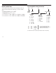
Chapter 3 – Installation and Wiring ASSEMBLY OF SMP-3 OVERLOAD RELAY TO CONTACTOR The following figures illustrate the steps necessary to assemble the SMP-3 overload relay to a contactor. Figure 3.1 Assembly of SMP-3 Overload Relay to Contactor (applicable to Cat. No. 193-C1_1 and Cat. No. 592-C1_T) 2.8 Nm 25 lb-in Note: A Cat. No. 193-C1_1 or Cat. No. 592-C1_T must be mounted to the contactor prior to fastening the contactor to a panel.
Chapter 3 – Installation and Wiring Figure 3.2 Assembly of SMP-3 Overload Relay to Contactor (applicable to Cat. No.
Chapter 3 – Installation and Wiring Figure 3.3 Bulletin 109 Starter Dimensions (with SMP-3 Overload Relay) ➊ K H C G J F E B A D ➊ Refer to dimensions shown in Table 3A.
Chapter 3 – Installation and Wiring Table 3.A Bulletin 109 Starter Dimensions (with SMP-3 Overload Relay) ➊ Contactor Cat. No. A Width B Height C Depth D E F G H J➋ K 100–A09, –A12 70 (2-49/64) 165.8 (6-17/32) 84 (3-5/16) 117.1 (4-5/8) 76.3 (3) 60 (2-3/8) 50 (1-31/32) 35 (1-25/64) –15.7 (–5/8) 45 (1-13/16) 100–A18, –A24 70 (2-49/64) 174.4 (6-7/8) 92 (3-5/8) 122.4 (4-53/16) 87.1 (3-7/16) 75 (2-61/64) 60 (2-3/8) 35 (1-25/64) –4.
Chapter 3 – Installation and Wiring Figure 3.4 Bulletin 509 Starter Dimensions (with SMP-3 Overload Relay) ➊ B G E H F D A ➊ Refer to dimensions found in Table 3.B.
Chapter 3 – Installation and Wiring Table 3.B Bulletin 509 Starter Dimensions (with SMP-3 Overload Relay) NEMA Size A Width B Height C Reset Depth D E F Dia. G H 0–1 90.4 (3-9/16) 248.3 (9-3/4) 117.7 (4-5/8) 69.9 (2-3/4) 234.4 (9-1/4) 5.15 (13/64) 41.8 (1-21/32) 87 (3-27/64) 2 100 (3-5/16) 273.6 (10-49/64) 117.7 (4-5/8) 80 (3-5/32) 260.2 (10-1/4) 5.54 (7/32) 41.8 (1-41/64) 92.2 (3-5/8) 3 155 (6-1/8) 370 (14-9/16) 151 (5-5/16) 140 (5-33/64) 220 (8-21/32) 7.1 (9/32) 45.
Chapter 3 – Installation and Wiring Figure 3.5 Panel Mount Assembly Dimensions (Cat. No. 193–C1_1 used with Cat. No. 193-BPM4) 70 (2.76) 122.1 (4.81) 3.69 (.15) 35mm DIN rail 126 (4.96) 6 (24) 87 (3.43) 61.7 (2.
Chapter 3 – Installation and Wiring Figure 3.6 Panel Mount Assembly Instructions for Cat. No. 193-BPM4 2 1 1.8 N-m 16 lb-in 4 3 Note: Must remove contactor adapter before assembling the SMP-3 overload relay and Cat. No. 193-BPM4.
Chapter 3 – Installation and Wiring Figure 3.7 Panel Mount Assembly Dimensions (Cat. No. 193-C1_3 used with Cat. No. 193-BPM5) 90 (3.54) 80 (3.15) 5.5 (22) 4 - Holes To Top of Reset 124.5 (4.90) 144.5 (5.69) 127 (5.00) 115 (4.53) 87.65 (3.45) 6 (,24) 81.8 (3.22) 5 (.2) 3-10 Á mm (inches) 3.69 (.
Chapter 3 – Installation and Wiring Figure 3.8 Panel Mount Assembly Instructions for Cat. No. 193-BPM5 1 2 3 Note: Must remove contactor adapter before assembling the SMP-3 overload relay and Cat. No. 193-BPM5.
Chapter 3 – Installation and Wiring Figure 3.9 Panel Mount Assembly Dimensions (Cat. No. 193-C1L7 and 193-C1M7) TO TOP OF RESET 141 (5.55) 119 (4.69) 105 (4.13) B A 6.8 (.27) RESET COMM REMOTE RESET 11.8 (.46) 90 (3.54) Ø 5.6 (.22) 4 - HOLES mm (inches) Table 3.C Panel Mount Assembly Dimensions (Cat. No. 193-C1L7 and 193-C1M7) 3-12 Cat. No. Current Range (Amperes) 193–C1L7 20–90 193–C1M7 40–180 Dimension A 158 (6.22) 188.3 (7.41) Dimension B 46.2 (1.82) 60.8 (2.
Chapter 3 – Installation and Wiring Short Circuit Ratings Table 3.D SMP-3 Short Circuit Ratings The SMP-3 overload relay is suitable for use on a circuit capable of delivering not more than the RMS symmetrical amperes, 600 volts maximum, as listed in Table 3.D . Cat. No.
Chapter 3 – Installation and Wiring Table 3.E Wire Size and Torque Specifications (Continued) Cat. No. Cat (XXX= XXX= 592 or 193) 193-C1_2 193-C1_3 592-C1_C 193-C1_4 592-C1_D 193-C1_5 592-C1_E 193-C1N6 592-C1NF 592-C1NG 193-C1P6 592-C1PF 592-C1PG 193-C1R6 592-C1RF 592-C1RG 193-NX15 193-NX16 193-NX17 3-14 Min. Wire Capacity Power Terminals Max. Wire Capacity Metric (mm2) AWG Metric (mm2) AWG Lug Nm (Lb-in) 0.7-75 2.
Chapter 3 – Installation and Wiring Table 3.F specifies the srew size needed to secure the green ground wire of the SMP-3 overload relay to earth ground. Table 3.G Control Terminal Block Designation Table 3.F Ground Screw Specifications Cat. No. Screw Type Terminal Description 10 Out A ➊ 20 Out B ➊ Standard Metric 30, 40 Normally Closed Contact ➋ 193-C1_1, 2, or 3 592-C1_T, A, or C No.
Chapter 3 – Installation and Wiring Figure 3.11 Typical Motor Connections S.C.P.D. A1 S.C.P.D.
Chapter 3 – Installation and Wiring Typical Control Circuit Wiring Diagrams ATTENTION: The ratings of the SMP-3 triacs and trip relay must not be exceeded. If the coil current or voltage of the contactor exceeds the triac or relay rating an interposing relay must be used. ATTENTION: When power is applied to SMP-3 terminals “50” and “60,” the N.O. relay across “30” and “40” closes. ATTENTION: Additional control circuit protection may be required. Refer to National Electrical Code.
Chapter 3 – Installation and Wiring Figure 3.12 SMP-3 Starter Wiring Diagram (with Triac Control) L1 L2 Figure 3.13 SMP-3 Starter Wiring Schematic (with Triac Control) L3 To 120/240V AC Supply Control Circuit Fuses (When Used) OUT A SMP-3 ÌÌ 20 30 OUT B 40 50 To 120V AC or 240V AC Supply 60 30 40 ➊ Applicable to Cat. No. 193-C1_1, 2,3,4, and 5, 592-C1_T, A, C, D, and E. ➋ The coil voltage and supply voltage must be the same. (i.e.120V AC or 240V AC).
Chapter 3 – Installation and Wiring Figure 3.14 SMP-3 Starter Wiring Diagram (with Push Button Control) L1 L2 Figure 3.15 SMP-3 Starter Wiring Schematic (with Push Button Control) To 120/240V AC Supply L3 Control Circuit Fuses (When Used) ÌÌ Ì ÌÌÌ START ÌÌ ÌÌÌ ÌÌ ÌÌ ÌÌÌ ÌÌ ÌÌ ÌÌ ÌÌ ÌÌ STOP STOP M 30 40 SMP-3 M M SMP-3 50 SMP-3 60 10 OUT A ➊ Applicable to Cat. No. 193-C1_1, 2,3,4,and 5, 592-C1_T, A, C, D, and E. 20 30 OUT B ➋ The coil voltage and supply voltage must be the same. (i.e.
Chapter 3 – Installation and Wiring Figure 3.16 CT-Mounted SMP-3 Starter Wiring Diagram (with Triac Control) Figure 3.17 CT-Mounted SMP-3 Starter Wiring Schematic (with Triac Control) L1 CR SMP-3 OUT A 20 OUT B 30 FUSE 40 TRIP RELAY L1 60 30 40 To Voltage Source L3 ÌÌ ÌÌ M CT1 CR CT3 CT2 ➊ Applicable to Cat. No. 193-C1_6, 592-C1_F and G. ➋ The supply voltage to the SMP-3 overload must be 120 V AC. 120/240V AC P/S Note: Refer to page 3-17 for wiring ATTENTIONS.
Chapter 3 – Installation and Wiring Figure 3.18 SMP-3 Reversing Starter Wiring Diagram (with Triac Control) Figure 3.19 SMP-3 Reversing Starter Wiring Schematic (with Triac Control) To 120/240V AC Supply L1 L2 L3 Control Circuit Fuses (When Used) OUT A SMP-3 ÌÌ ÌÌ ÌÌ ÌÌ REV OUT B SMP-3 10 30 FOR REV 20 40 SMP-3 REV FOR FOR ÌÌ ÌÌ ÌÌ ÌÌ ÌÌ ÌÌ 50 SMP-3 60 ➊ Applicable to Cat. No. 193-C1_1, 2,3,4,and 5, 592-C1_T, A, C, D, and E.
Chapter 3 – Installation and Wiring Figure 3.20 SMP-3 Reversing Starter Wiring Diagram (with Push Button Control) Figure 3.21 SMP-3 Reversing Starter Wiring Schematic (with Push Button Control) To 120/240V AC Supply L1 L2 L3 ÌÌÌÌ ÌÌ STOP FOR REV FOR REV ÌÌ ÌÌ ÌÌ ÌÌ REV FOR REV FOR ÌÌ ÌÌ ÌÌ FOR REV STOP OUT A 20 OUT B 30 FUSE TRIP RELAY 40 60 REV SMP-3 60 ➋ The coil voltage and supply voltage must be the same. (i.e.120V AC or 240V AC).
Chapter 3 – Installation and Wiring Figure 3.22 CT-Mounted SMP-3 Reversing Starter Wiring Diagram (with Triac Control) Figure 3.
Chapter 3 – Installation and Wiring Figure 3.
Chapter 3 – Installation and Wiring Figure 3.25 SMP-3 Multi-speed Starter Wiring Schematic (with Triac Control) To 120/240V AC Supply Control Circuit Fuses (When Used) OUT A SMP-3 (High) OUT B SMP-3 (Low) 10 ÌÌ ÌÌ ÌÌ ÌÌ ÌÌ ÌÌ ÌÌ ÌÌ High Low 10 30 40 30 SMP-3 (Low) 40 SMP-3 (High) Low High 50 50 SMP-3 (Low) 60 SMP-3 (High) 60 ➊ Applicable to Cat. No. 193-C1_1, 2,3,4,and 5, 592-C1_T, A, C, D, and E. ➋ The coil voltage and supply voltage must be the same. (i.e.120V AC or 240V AC).
Chapter 3 – Installation and Wiring Figure 3.
Chapter 3 – Installation and Wiring Figure 3.27 SMP-3 Multi-speed Starter Wiring Schematic (with Push Button Control) To 120/240 V AC Supply Control Circuit Fuses (When Used) ÌÌ ÌÌ ÌÌÌ ÌÌÌÌ ÌÌ ÌÌ ÌÌÌ ÌÌ ÌÌ ÌÌÌ ÌÌ ÌÌ ÌÌ ÌÌ STOP H L Low High 40 30 SMP-3 (Low) Low L 30 40 SMP-3 (High) H High Low High 50 50 SMP-3 (Low) SMP-3 (High) 60 60 ➊ Applicable to Cat. No. 193-C1_1, 2,3,4,and 5, 592-C1_T, A, C, D, and E. ➋ The coil voltage and supply voltage must be the same. (i.e.
Chapter 3 – Installation and Wiring Figure 3.
Chapter 3 – Installation and Wiring Figure 3.29 CT-Mounted SMP-3 Multi-speed Starter Wiring Schematic (with Triac Control) To 120V AC Supply To Voltage Source Control Circuit Fuses (When Used) OUT A SMP-3 (High) OUT A SMP-3 (Low) 10 ÌÌ ÌÌ ÌÌ ÌÌ ÌÌ ÌÌ ÌÌ CRH CRL 10 30 40 30 SMP-3 (Low) Control Circuit Fuses (When Used) 40 SMP-3 (High) High CRH Low CRL High Low CRL CRH 50 50 SMP-3 (Low) SMP-3 (High) ÌÌÌ ÌÌÌ ÌÌÌ ÌÌÌ 60 60 ➊ Applicable to Cat. No. 193-C1_6, 592-C1_F and G.
Chapter 3 – Installation and Wiring Figure 3.30 Remote Reset Wiring Diagram P2 P1 L1 (+) L2 (–) Contact A (NO) Jumper A P1 (Black Wire) P2 (Brown Wire) Jumper B L Bulletin 800T–NX131 (Back View) Bulletin 1202 Cable Table 3.H Remote Reset Cable Selections 3-30 Catalog Number “L” Dimension 1202–RRC1 1 Meter (3.28 Ft.) 1202–RRC3 3 Meters (9.84 Ft.) 1202–RRC6 6 Meters (19.69 Ft.) 1. Connect a jumper wire (A) from the L1(+) terminal to one of the N.O.
Chapter 3 – Installation and Wiring Figure 3.31 Communication Adapter Mounting Distances and the Cable Connections Male–Male Cable ➊ A Maximum Distance A ≤ 10 Meters Bulletin 1202 Cable Port 1 Pull back connector to disconnect cable from adapter device or port 1 connection.
Chapter 3 – Installation and Wiring CONFIGURING THE SMP-3 OVERLOAD RELAY The SMP-3 overload relay contains 14 DIP switches for configuring the trip characteristics of the SMP-3 overload relay. These DIP switches are located on the front of the device under the anti-tamper shield. These DIP switches are used to set the trip class, manual or automatic reset mode, ground fault detection, jam detection, test, and the full load current of the SMP-3 overload relay as shown below:.
Chapter 3 – Installation and Wiring Setting Auto/Manual Reset – The Auto/Man reset DIP switch is used to establish the “overload” reset mode of the SMP-3. Auto/Man DIP Switch • • Auto Man Automatic Reset – The SMP-3 overload relay is set to automatic reset mode by placing the Man/Auto DIP switch in the “ON” or “Auto” postion. In the “Auto” reset mode, an overload fault on the SMP-3 overload relay will automatically be reset after the appropriate reset delay time (See Reset Delay Times in Chapter 4).
Chapter 3 – Installation and Wiring Selecting Ground Fault (GF), Jam/Stall, and Test Functionality DIP Switch Setting • ON Ground Fault (GF) – The ground fault feature of the SMP-3 overload relay is enabled by placing the GF DIP switch in the “ON” position. When the ground fault is enabled, the SMP-3 overload relay will trip if an equipment ground fault of 50% of the full load current setting exists for 0.
Chapter 3 – Installation and Wiring Setting the Full Load Current (FLC) The full load current is set with the eight FLC DIP switches. Above each DIP switch on the front of the SMP-3 overload relay a number identifies the current associated with that particular DIP switch. The total FLC setting is the sum of all the currents for the DIP switches set in to ON position. The rated current (the current above which the SMP-3 overload relay will ultimately trip) is 120% of the full load current setting.
Chapter 3 – Installation and Wiring Table 3.I FLC DIP Switch Designations and Minimum Settings Catalog Number er ➊ xxx–C1Dx xxx–C1Fx xxx–C1Hx xxx–C1Kx xxx–C1Lx xxx–C1Mx xxx–C1Nx xxx–C1Px xxx–C1Rx ➊ ➋ Current Range LC (FLC Range) (0.7–2.5A) (2–10A) (8–37A) (20–75A) (20–90A) (40–180A) (70–304A) (100–414A) (140–608A) FLC Switch Designations SW1 SW2 SW3 SW4 SW5 SW6 SW7 SW8 1.00 5.0 15.0 30 40 75 150 200 300 0.70 2.0 10.0 20 25 50 75 100 150 0.40 1.0 5.0 10 10 25 40 50 80 0.20 1.0 4.
Chapter 3 – Installation and Wiring FLC SETTING FOR APPLICATIONS IN USA AND CANADA Motors with a Service Factor of 1.15 or greater: set the full load current to the nearest value of the motor current taken from the motor nameplate. Motors with Service Factor of less than 1.15: set the full load current to the nearest value of 90% of the motor current taken from the motor nameplate.
Chapter 3 – Installation and Wiring 3-38
Functional Description CHAPTER OBJECTIVES This chapter describes the functionality and features of the SMP-3 overload relay. SMP-3 INPUTS/OUTPUTS Configuration Dip Switches The SMP-3 overload relay contains 14 configuration DIP Switches. The six left-most DIP switches are used to configure the trip class (2), establish the Auto/Man Reset Mode (1), enable/disable Ground Fault (1), enable/disable Jam/Stall (1), and to induce a Test Trip (1).
Chapter 4 – Functional Description ATTENTION: Noise suppression circuitry across OUT A and OUT B inside the SMP-3 overload relay allows leakage current to flow when the output is in the off-state. See Appendix A for leakage current. Trip Relay The SMP-3 overload relay contains a Normally Open trip relay across terminals 30 and 40 (See Appendix A for Trip Relay ratings and recommended fusing). When power is applied to an unfaulted SMP-3 overload relay, the trip relay will close.
Chapter 4 – Functional Description SMP-3 PROTECTION FEATURES Figure 4.1 SMP-3 Trip Curves – Class 10 The SMP-3 overload relay provides four primary forms of motor protection: Overload, Phase Loss, Ground Fault, and Jam/Stall Protection. 1000.0 Overload protection is an embedded feature of the SMP-3 overload relay. The SMP-3 overload relay provides overload protection by monitoring the maximum phase of motor current, and then using that data to calculate the overload’s thermal capacity utilized.
Chapter 4 – Functional Description 10000.0 10000.0 1000.0 1000.0 100.0 10.0 1.0 1 2 3 4 5 6 7 8 910 Multiples of Full Load Current Approximate trip time for 3-phase balanced condition from cold start. 4-4 Figure 4.3 SMP-3 Trip Curves – Class 20 Approximate Trip Time (sec.) Approximate Trip Time (sec.) Figure 4.2 SMP-3 Trip Curves – Class 15 Approximate trip time for 3-phase balanced condition from hot start. 100.0 10.0 1.
Chapter 4 – Functional Description Figure 4.5 SMP-3Trip Curve after Auto Restart 10000.0 100000 1000.0 1000 100.0 100 10.0 Seconds Approximate Trip Time (sec.) Figure 4.4 SMP-3 Trip Curves – Class 30 Class 10 10 Class 15 Class 20 Class 30 1.0 1 2 3 4 5 6 78910 Multiples of Full Load Current Approximate trip time Approximate trip time for 3-phase balanced condifor 3-phase balanced condition from hot start. tion from cold start.
Chapter 4 – Functional Description Auto/Man Reset. The Auto/Man configuration DIP switch is used to select the overload reset mode of the SMP-3 overload relay. If Auto Reset (automatic reset) mode is selected, the SMP-3 overload relay will automatically reset after an overload fault after the appropriate reset delay time has expired.
Chapter 4 – Functional Description Note: In Wye-Delta motor applications, the trip threshold is ≥ 25% of the FLA Setting The ground fault protection feature of the SMP-3 overload relay can only be used in three-phase applications. The ground fault configuration DIP switch must be placed in the OFF position for single-phase applications. Jam/Stall Protection Jam/Stall protection is enabled or disabled by placing the Jam/Stall configuration DIP switch in the ON or OFF position, respectively.
Chapter 4 – Functional Description Remote Reset Communications The SMP-3 provides a REMOTE RESET port to which a remote reset push-button (Allen-Bradley Cat. No. 800T-NX1311) can be connected to using a Bulletin 1202 Remote Reset Cable (See Remote Reset Wiring Diagram and Cable Selection in Chapter 3 for more information).
Chapter 4 – Functional Description Communication Parameters. The following is list of the parameters that the SMP-3 overload relay can communicate to an adapter. [Average Current] This parameter is the average value of the three-phase current passing through the SMP-3 overload relay. The accuracy of the average current reported to a communication adapter is ± 5% [FLC Setting] This parameter is the actual Full Load Current (FLC) setting established by the eight FLC DIP switches.
Chapter 4 – Functional Description Communication Parameters. (cont.) [Firmware Revision] Parameter # The firmware revision number identifies the release of the logic code that is controlling the SMP-3 overload relay. If contacting the factor regarding a problem, be prepared to provide this number. [Device Port #] Parameter Type Units Parameter # This parameter identifies the port that the adapter being used to monitor the parameter is connected to.
Chapter 4 – Functional Description Communication Parameters. (cont.) [Mask] Parameter # The mask parameter can be used to program or identify the communication adapter devices that are enabled and/or disabled. Refer to Chapter 8 for Logic Mask Programming instructions Parameter Type Units 7 Factory Default Read/Write Byte Bit 7 6 5 4 3 2 1 0 X X X X X X This parameter is a 16 bit common status message interpreted by the HIM and transmitted by all serial port master devices.
Chapter 4 – Functional Description Table 4.
Chapter 4 – Functional Description Human Interface Module Adapter. The Human Interface Modules were designed to allow users to locally program, monitor, and/or control master devices (such as SMP-3 overload relays, Drives, or SMCs). The SMP-3 overload relay can communicate directly to a Drive HIM (1201-HA_) or a SMP-3 HIM (193-HIM1). However, since the SMP-3 HIM was designed specifically for the SMP-3 overload relay, it provides more functionality than the Drive HIM when used with the SMP-3.
Chapter 4 – Functional Description 4-14
Chapter Human Interface Module program the SMP-3 overload relay CHAPTER OBJECTIVES Chapter 5 describes the various controls and indicators found on the SMP-3 Human Interface Module (HIM) and the Drive HIM. view operating parameters The control panel enables the user to: control output A HIM DESCRIPTION control output B Each HIM shown has two panels: a display panel and a control panel. The display panel enables the user to: reset the SMP-3 overload relay Figure 5.1 SMP-3 HIM Figure 5.
Chapter 5 – Human Interface Module DISPLAY PANEL DESCRIPTIONS CONTROL PANEL DESCRIPTION Note: The following display panel descriptions apply to both the SMP-3 HIM and the Drives HIM. SMP-3 HIM Control Panel Description ESC SEL Escape Use this key to cause the programming system to go back one level in the menu structure. Select Use this key to indicate which line of the display should be active. The first character of the active line will flash.
Chapter 5 – Human Interface Module SMP-3 HIM LED Indicators OUT B Out B ON Press this green key to energize output B (terminal 20). This functionality can be masked out. Press this red key to de-energize output B (terminal 20). OUT A&B Press this red key to simultaneously de-energize outputs A and B (terminals 10 and 20, respectively). Fault This LED is illuminated when the HIM is connected to a faulted SMP-3 overload relay.
Chapter 5 – Human Interface Module Drives HIM Control Panel Description Press this green key to energize output A (terminal 10). This functionality can be masked out. Press this red key to turn off both output A and B. Pressing the same red key to reset the SMP-3 overload relay when a fault exists. When a HIM is connected to a SMP-3 overload relay, the HIM display will display a series of start-up screens (as indicated in Chapter 7). Eventually, it will display a default status display.
Chapter 5 – Human Interface Module Note: Earlier versions of the HIM may require the user to press ESC (Escape key) to return to the fault default status display. HIM MODES The SMP-3 HIM supports four modes: display, program, search, and control status mode. The menu structures are dictated by the master device. So a drive HIM used with a SMP-3 overload relay will provide the same menu scheme and modes as a SMP-3 HIM used with a SMP-3 overload relay. (Assuming both have the same code release).
Chapter 5 – Human Interface Module DESCRIPTION ACTION ESC SEL 1. Press any key to go from the Status Display to the Choose Mode menu. 2. Press the up/down keys to toggle to “Display” in the display. 3. Press Enter to go to the Display menu. (If this is the first time that the display mode is entered since the last power-up, the display will start with parameter 1. Otherwise the display will start with the last parameter displayed). The parameter number is located on the right side of the value line.
Chapter 5 – Human Interface Module Program Mode Control Status Mode When selected, the program mode is used to view the SMP-3 communication parameters or program the SMP-3 Logic Mask parameter. The difference between Program and Display Mode is that in Program Mode the first character of the text line flashes to indicate that the parameter value can modified. Refer to Chapter 8 for instructions on programming. When selected, the Control Status mode allows you to quickly mask out/disable the HIM.
Chapter 5 – Human Interface Module HIM INSTALLATION AND REMOVAL Removal Installation The HIM can be disconnected from the SMP-3 overload relay in one of two ways: The HIM can be used as a hand-held terminal or it can be mounted on the front of an enclosure. The HIM connects to the SMP-3 overload relay via a SCANport cable plugged into the “COMM” port on the front of the SMP-3 overload relay.
Chapter Serial Communication COMMUNICATIONS USING BULLETIN 1203 COMMUNICATION MODULES The SMP-3 overload relay can communicate its parameter data to a PLC, SLC, or other logic controller by using an optional Bulletin 1203 communications module. The amount of information that is transferred between the SMP-3 overload relay and the logic controller is determined by the DIP switch settings on the communication module.
Chapter 6 – Serial Communication Logic Control Data The information in Table 6.B illustrates the logic control data that is sent to the SMP-3 overload relay through the logic controller output image table. When using the Bulletin 1203-GD1 communication module, this information is sent to the SMP-3 overload relay when SW3 dip 2 on the 1203-GD1 module is ON. Table 6.
Chapter 6 – Serial Communication SMP-3 Status Data The information in Table 6.C illustrates the SMP-3 overload relay status data that is sent to the logic controller input image table from the SMP-3 overload relay. When using the Bulletin 1203-GD1 communication module, this data will be sent to the PLC from the SMP-3 overload relay when SW3 dip 2 on the 1203-GD1 module is ON.
Chapter 6 – Serial Communication Table 6.C SMP-3 Status Data Bit 15 14 13 12 11 10 9 8 7 6 5 4 3 2 1 X X X X X X X X X X X X X X X Note: The next 16 bit word following the 16 bit Status Data word is the unscaled analog value of the parameter selected by bits 13–15 in the Logic Control Data word.
Chapter 6 – Serial Communication Scale Factor Conversion When reading the average current parameter data in the logic controller’s input table, divide these values by the scaling values shown in Table 6.D to determine the “display units.” Table 6.D Average Current and FLC Setting Scaling Current Range (FLC Range) Scaling Factor ➀ 0.7–2.
Chapter 6 – Serial Communication SAMPLE PROGRAM LISTING FOR REMOTE I/O TO SERIAL PORT COMMUNICATION The diagram shown below reflects the memory configuration used in the sample ladder logic program shown in the remaining portion of this chapter. Figure 6.1 Typical SMP-3 R/IO Communication Block Diagram Contactor SMP-3 PLC-5 Gateway Logic Control Data PanelView ➀ Logic Control Data ( Table 6.B) from logic controller’s output image table.
Chapter 6 – Serial Communication The following section outputs the OUT A status, OUT B status, and Control status of the SMP-3 overload relay to a local rack and Panelview address.
Chapter 6 – Serial Communication The following section determines the value of the selected analog parameter sent from the SMP-3, and sends that value to the corresponding destination of a Panelview. The Panelview destination is determined by the analog feedback designator from the SMP (Rack 2, Word 0, Bits 5–7).
Chapter 6 – Serial Communication Rung 2:5 Current Unbalance to Rack 3,Word 3 | I:020 I:020 I:020 +MOV–––––––––––––––+ | +––] [–––]/[–––]/[––––––––––––––––––––––––––––––––––––––––+MOVE +–+ | 07 06 05 |Source I:021| | | | 0| | | |Destination O:033| | | | 0| | | +––––––––––––––––––+ | The following section displays the SMP-3 fault status on the panelview. Rung 2:6 Copy Fault status bits from SMP Status (Rack 2,Word 0, Bits 8–15) to buffer N31:1 bits 0–7 for comparison purposes.
Chapter 6 – Serial Communication Set appropriate fault bit in word sent to Panelview (Rack 1, Word 0, Bit 8–15) based on fault code from SMP (Rack 2, Word 0, Bit 8–15 copied to N31:1) Rung 2:8 | +CMP–––––––––––––––+ O:010 | +–+COMPARE +––––––––––––––––––––––––––––––––––––––––––––––––––––( )––+ | |Expression | 10 | | |N31:1 = 1 | | | +––––––––––––––––––+ | Rung 2:9 | +CMP–––––––––––––––+ O:010 | +–+COMPARE +––––––––––––––––––––––––––––––––––––––––––––––––––––( )––+ | |Expression | 11 | | |N31:1 = 2 | | | +––
Chapter 6 – Serial Communication Rung 2:13 | +CMP–––––––––––––––+ O:010 | +–+COMPARE +––––––––––––––––––––––––––––––––––––––––––––––––––––( )––+ | |Expression | 15 | | |N31:1 = 6 | | | +––––––––––––––––––+ | Rung 2:14 | +CMP–––––––––––––––+ O:010 | +–+COMPARE +––––––––––––––––––––––––––––––––––––––––––––––––––––( )––+ | |Expression | 16 | | |N31:1 = 7 | | | +––––––––––––––––––+ | Rung 2:15 | +CMP–––––––––––––––+ O:010 | +–+COMPARE +––––––––––––––––––––––––––––––––––––––––––––––––––––( )––+ | |Expression | 1
Chapter 6 – Serial Communication The following section of code transfers commands from the local rack control switches to the SMP-3 overload relay. These commands control OUT A and OUT B, reset faults, and establish the analog parameter that is to accompany the status word from the SMP-3 overload relay. Rung 2:16 Output Local Rack Control Switches (Rack 0,Word 1,Bit 0–4) to SMP (Rack 2,Word 0, Bit 0–4).
Chapter 6 – Serial Communication The following section of code allows the analog parameter to be manually or automatically selected. The mode of operation is selected with Rack 0, Word 1, Bit 3: Set = automatic mode Clear = manual mode In manual mode the analog parameter is selected via Rack 0, Word 1, Bit 5, 6, 7. In automatic mode the analog parameter is selected via the code.
Chapter 6 – Serial Communication Rung 2:19 Auto Parameter Selection Start 30ms Timer to determine when to increment to next parameter | I:010 +TON–––––––––––––––+ | +––] [–––––––––––––––––––––––––––––––––––––––––––––––+TIMER ON DELAY +–(EN)–+ | 03 |Timer T4:0| | | |Time base 0.
Chapter 6 – Serial Communication Rung 2:22 Auto Parameter Selection Output automatic parameter selection (N31:1, bit 0–2) to SMP command word (Rack2,word 0, bit 13–15) | I:010 +BTD–––––––––––––––+ | +––] [––––––––––––––––––––––––––––––––––––––––––––––––––––+BIT FIELD DISTRIB +–+ | 03 |Source N31:3| | | | 3| | | |Source bit 0| | | |Destination O:020| | | | 24| | | |Destination bit 13| | | |Length 3| | | +––––––––––––––––––+ | | | +––––––––––––––––––––––––––––––––[END OF FILE]–––––––––––––––––––––––––––––––––
Chapter 6 – Serial Communication 6-16
Chapter Start Up 7 CHAPTER OBJECTIVES START-UP PROCEDURE This chapter describes the steps necessary to ensure proper start-up of the SMP-3 overload relay. The information contained in the previous chapters must be read and understood before proceeding. The following start-up procedure is written for SMP-3 applications with Human Interface Modules. For application without HIMs, disregard steps 5 and 6.
Chapter 7 – Start Up A. The HIM ID# and firmware version number HIM ID # Version X.XX B. Communication status HIM ID # Connecting... HIM ID # Connected C. Series letter of SMP-3 overload relay D. Status of outputs A and B (this display will remain until changes are made or a fault occurs.) SMP-3 Series X A=OFF B=OFF 0.0 AMPS Note: The HIM may be plugged into SMP-3 overload relay at any time after being powered up and communication with the HIM will be established. ❏ 6.
Chapter Programming CHAPTER OBJECTIVES Chapter 8 describes the programming procedure for the SMP-3 overload relay. The Logic Mask is the only SMP-3 programmable parameter. LOGIC MASK PARAMETER The Logic Mask parameter can be used to mask (disable) or unmask (enable) either an HIM or communication module. When an adapter is masked, its control functionality over the SMP-3 is disabled. Conversely, when an adapter is not masked, its control functionality over the SMP-3 is completely enabled. 8 Figure 8.
Chapter 8 – Programming Conversely, when a Logic Mask bit is set to “0,” the adapter connected to the respective part is disabled. 00000X00 – Port ID #1 is disabled. 000000X0 – Port ID #2 is disabled. 00000000 – Port ID #1 and #2 are disabled Note: If the SMP-3 HIM is disabled/masked out, the ON and RESET buttons will be disabled and the Start/Reset Disabled LED will be energized.
Chapter 8 – Programming Mask Programming (Using the HIM in Program Mode) The following procedure describes the programming steps required to mask out any communication adapter using the HIM in program mode. DESCRIPTION ACTION ESC SEL To Select Mode or 1. Press any key to go from the Status Display to the Choose Mode menu. 2. Press the up/down keys to toggle to “Program” in the display. 3. Press Enter to go to the Program menu. 4. Press the up/down keys until Device Port # appears. 5.
Chapter 8 – Programming Mask Programming (Using the HIM in Control Status Mode) The following procedure describes the programming steps required to mask out the HIM using the control status mode. Note: Earlier versions of the HIM may not support this mode. DESCRIPTION ACTION ESC SEL 1. Press any key to go from the Status Display to the Choose Mode menu. 2. Press the up/down keys to toggle to “Control Status” in the display. 3. Press Enter to go to the Control Status menu. 4.
Chapter Troubleshooting and Fault Information CHAPTER OBJECTIVES This chapter provides information about: LED diagnostics General troubleshooting procedures SMP-3 fault information LED DIAGNOSTICS The SMP-3 overload relay contains four status LEDs that are intended to aid in troubleshooting and performing fault diagnostics on the SMP-3 overload relay. Power This green LED, when illuminated, indicates that power is applied to terminals 50 and 60.
Chapter 9 – Troubleshooting and Fault Information GENERAL TROUBLESHOOTING PROCEDURES The following steps are a few techniques that can be used to troubleshoot the SMP-3. Failure Type 9-2 General Problem Action to Take OUT A or OUT B OUT A or B do not appear to turn on when 1. Check the supply voltage. commanded to do so. 2. Remove power from the SMP-3 overload relay, then check the wiring to control terminals 10 and 20. 3. Check for a fault condition.
Chapter 9 – Troubleshooting and Fault Information Failure Type General Problem Action to Take Trip Relay The trip relay does not appear to be functioning correctly. 1. Remove power from the SMP-3 overload relay, then check the wiring to control terminals 30 and 40. 2. Induce a Test fault on the SMP-3 by turning the Test DIP switch On. The SMP-3 overload relay should fault and the Trip LED should flash one time. There should also be an audible click corresponding to the trip relay opening.
Chapter 9 – Troubleshooting and Fault Information Failure Type General Problem Action to Take Communication The communication link between the 1. Check the HIM display (if applicable). If the display appears to be cycling between menus: SMP-3 and an adapter does not appear to a. Check the communication connection per the procedure described in Table 9.B for a be functioning. Comm Fault. b. Induce a Test fault on the SMP-3 overload relay. If the SMP-3 overload relay does not trip, consult the factory.
Chapter 9 – Troubleshooting and Fault Information FAULT INFORMATION HIM Display. When an HIM is connected to a faulted SMP-3 overload relay, a brief fault description will be displayed on the text line of the HIM display. and a fault code will be displayed on the value line of the HIM display, as shown below. Figure 9.1 Fault Display ATTENTION: Resetting a fault will not correct the cause of the fault condition. Corrective action must be taken to fix the fault cause before resetting the fault.
Chapter 9 – Troubleshooting and Fault Information Table 9.A Fault Codes Fault Description ➀ Number of Flashes HIM Fault Text HIM Fault Code Protection Fault ➀ Reset Test 1 Trip/Test F1 Manual Overload 2 Overload F2 ✓ Auto/ Manual Phase Loss 3 Phase Loss F3 ✓ Manual Ground Fault 4 Ground Fault F4 ✓ Manual Jam/Stall 5 Jam/Stall F5 ✓ Manual
Chapter 9 – Troubleshooting and Fault Information Table 9.B Fault Descriptions Fault Name and Number Test F1 Overload F2 Phase Loss F3 Ground Fault F4 Fault Description The TEST DIP switch on the SMP-3 overload relay is ON. Action to Take Turn off the TEST DIP switch and reset the SMP-3 overload relay. The SMP-3 overload relay detected current greater than the trip 1. Check the motor for excessive load. rating of the SMP-3 overload relay for a period of time such that 2.
Chapter 9 – Troubleshooting and Fault Information Table 9.B Fault Descriptions (cont.) Fault Name and Number Jam/Stall F5 Illegal FLC Setting F6 Fault Description Action to Take The Jam DIP switch on the SMP-3 overload relay is ON, and 1. Ensure that the motor is free to rotate. greater than 400% of the FLC current for ≥0.5 second has been 2. Check the load and drive system for high friction or jam.
Appendix A – Specifications Table A.1 Specifications ELECTRICAL – CONTROL CIRCUIT OUT A and OUT B Outputs Power Supply Input Voltage Rating 110/240 VAC, 50/60 Hz Operating Range Type 85 to 264 VAC, 47–63 Hz Maximum Power Consumption 6 watts Maximum Power Interruption Time 20 ms.
Appendix A – Specifications ELECTRICAL – CONTROL CIRCUIT (cont.) ENVIRONMENTAL (Cont.) Motor Current Terminal Marking Phases Rated Insulation Voltage Maximum Operational Current Operational Frequency Current Wave Shape Three-phase or SIngle Phase 660 VAC (See Cat. No.
Appendix A – COMMUNICATIONS PARAMETER MONITORING Adapter Maximum current draw of all adapters should not exceed 200 mA Hand-held Adapter (HIM) Operational HIM (can be disconnected from the SMP-3 overload relay) Type of Display (HIM) HIM Controls Communication Adapter Specifications 16 character, 2 line LCD super twist with backlight Average Current FLC Setting Default parameter displayed and selectable as a displayed parameter Selectable as a displayed parameter Thermal Capacity Utilized Selecta
Appendix A – A-4 Specifications
Appendix B – SMP-3 Accessories ACCESSORIES Table B.1 SMP-3 Accessories Description Used with Cat. No. Pkg. Qty. 193-C1N6, 300A Terminal Lugs T 193-C1P6, 400A 199–LG1 3 193-C1R6, 600A 193–C1_3 193–BPM4 1 193–C1N6 , 300A Flexible B Bus Connector 193-C1P6, 400A Human Interface Module 193–BPM5 193–PCG1 3 193-C1R6, 600A Communication Module M 199–LH1 199–LJ1 193–C1_1, 193-C1_T DIN Rail/Panel Adapter Cat. No. 193–PCH1 193–PCJ1 SMP-3 – Remote I/O Comm.
SMP-3 Accessories Appendix B – Driv Table B.1 (cont.) Description Used with Cat. No. Pkg. Qty. Cable Length 1/3 meter Communication Cable Remote Reset Cable 193–C1_ , 592–C1_ 193–C1_ – , 592–C1_ 5 – 1 meter Cat. No.
Publication 193-5.0 - December 1996 PN 41052-053-01(B) Copyright ©2006 Rockwell Automation, Inc. All Rights Reserved. Printed in USA.