
Owner's manual


7-2 Troubleshooting
1901-UM020C-EN-P – June 2013
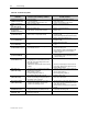
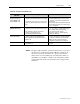
Table 7.B – Troubleshooting Guide
Problem orTrip
indicated
Indication of the following conditions Possible Solutions
Pullout trip (power factor)
[POWER FACTOR TRIP]
• Motor overloaded
• Loss of DC excitation
• Static exciter DC current level set too low
• Lessen the motor loading and/or overload
• Repair static exciter
• Increase current setting on static exciter
Squirrel-cage Protection
Trip
[SQ. CAGE PROT’N]
• Motor overloaded at start • Remove or lessen load for start
Incomplete Start Sequence
Time Exceeded
[INCOMPLETE START]
• Motor overloaded at start
• Field contactor or FC pilot relay coil failure
• Remove or lessen load for start
• Replace coil(s)
No Transducer Input
[PF–NO XDCR INPUT]
• The transducer is putting out less than 12 mA
when the motor is off (should be 12 mA)
• Check the wiring for the voltage sensing on the
transducer board.
• Replace phase angle transducer board if necessary.
• Replace analog card in SyncPro rack
CT Open/Shorted
[PF–CT OPEN/SHORT]
• The CT is either open or shorted. • Check the wiring between the CT and the
transducer board.
• Replace the CT if necessary.
CT Reversed
[PF–CT REVERSED]
• The CT is incorrectly wired to the transducer
board.
• Reverse the leads of the CT at the transducer
board.
No Signal @ SLC
[PF–NO SIGNAL@SyncPro]
• There is no signal at the SLC analog card from
the PF transducer board.
• Check the wiring between the transducer board
and the SLC analog card.
• Ensure that there is power to the transducer board.
• Replace the SLC analog card or transducer
board as required.
Transducer Problem
[PF–XDCR PROBLEM]
• The transducer is behaving unpredictably. • This is an all-encompassing fault and could
include anything from the CT, the transducer board,
or the SLC analog card.
PulseBoard24VFailure
[PULSE BOARD 24 V]
• Connection has not been made between the
analog/digital pulse board and the SyncPro DC
input card or from the discharge resistor to the
same A/D pulse board.
• 1746-P2 power supply has had a failure of the 24
V supply.
• Check the connections at the A/D pulse board.
• Check fuse in power supply. Check for 24 V at
power supply. Replace power supply if necessary.
• Replace A/D pulse board.
Field Voltage Loss
[FIELD VOLT LOSS]
• The static exciter is not actively producing DC or
the FVR relay coil has failed.
• Wrong polarity on FVR coil.
• Incorrect voltage rating of FVR coil.
• Exciter Enable (EE) relay did not pick up.
• Service the static exciter or repair the FVR relay.
• Check polarity on FVR coil.
• Check voltage rating of FVR coil.
• Verify the control circuit.
Field Current Loss
[FIELD AMPS LOSS]
• The current relay which monitors the motor field
current is not providing an energized contact to
verify that the static is functional.
• Check both the field current relay and the static
exciter for possible failures.
No Field Coil Feedback
[FIELD CONTACTOR]
• The SyncPro has requested the field contactor to
energize but the feedback contact from this
contactor is not showing as closed.
• The field contactor coil has failed. Replace the coil.
• The connection to the FC auxiliary has not been
made. Check the wiring.
• The FC auxiliary contact has failed. Replace the
contact.
Reversed PF @ SyncPro
[REVERSED PF@SLC]
• The connections from the PF transducer to the
analog card have been accidentally reversed.
• Switch the positive and negative transducer
output leads at the analog card.
External Hardware Fault
[EXTERNAL TRIP]
• An external device to the SyncPro is not
functioning as expected.
• Check external devices.