
Owner's manual


Setup and Commissioning 4-9
1901-UM020C-EN-P – June 2013
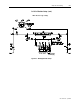
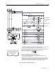
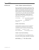
Figure 4.2 – Typical Schematic (Sheet 1 of 3)
SW1
21
ON
OFF
SW1
21
ON
OFF
To Customer Autoload Circuit if required
O:3/07
36
37
Autoload output
8
O:3/07
36
37
Autoload output
8
M Customer supplied equipment. Install any protective device external to the SyncPro in series in this
circuit as shown. Logic must be that contact is closed if running is permitted.
N FLC and TC are optional customer supplied inputs which are jumpered to terminal blocks if not used.
O Contact rating is 60 amp Make, 10 amp Break (inductive) – 10 amp continuous at 120V AC (A600)
P Refer to instruction manual for tap selection guidelines on RF1andRF2resistors.
Q Analog card switch settings are:
R Customer to take ground wire to ground bus (earth ground).
S Ground at bottom left hand mounting screw for rack or grounding bar.
T Line 1 to Line 2 voltage reference and Line 3 current reference must be maintained for proper
operation of the phase angle transducer.
U Wiring supplied on enclosed assembly only (1901-AADC10) for the open frame units. The customer
must supply these wires in addition to mounting the illuminated push button. DTAM, STAM cable
(1747-C10) and illuminated push button are supplied loose on open frame assemblies (1901-ANDC10).
V Output rating is 30 amp Make, 3 amp Break (inductive) – 3 amp continuous at 120V AC.
CT3CT2CT1
M
(+)
(-)
FC
FCFC
R1
R2
RF1 RF2
(+)
(-)
VPCGN
F1
F2
4.0A
SS
MR
ESR
FCR
SS
FC
SS
SS
ESR
ESR
R
21
78
C3A C3B
F2F1
T1
T2 T3
CPT
H1
H2
X1
X2
L
FVR
FLR
FC
TC
M
30
29
28
27
32
33
34
35
31
FCR
CR
M
12
1
2 3
4 5
6
7
98
20
IN0
IN2
IN1
5
6
IN0-
IN0+
BLK
C
26
ESR
BLK
R
W
BLK
C
1746-P1
I:4/03
I:4/04
I:4/05
I:4/06
I:4/07
I:4/08
I:4/02
MOV
I:4/00
I:4/01
O:3/06
O:3/00
O:3/01
O:3/02
O:3/03
O:3/04
F3
M
M
M
M
STOP
START
M
M
M
M
Q
M
M
M
M
M
M
M
M
M
M
M
M
M
M
M
N
N
O
O
P
P
T
S
T
FVR INPUT
FLR INPUT
FC INPUT
SYNCHRONIZATION ENABLE INPUT
EQUIPMENT SHUTDOWN INPUT
MAIN CONTACTOR INPUT
120
VAC
VAC
NEUT.
(Field Voltage Relay Input)
(Field Loss Relay Current)
(Field Contactor
Feedback Contact)
(Transition Complete)
(Reset Permitted)
(Main Contactor
Feedback Contact)
(Squirrel-Cage Protection Trip)
(Synchronous Pullout Trip)
(Incomplete Sequence Trip)
SCP Trip
Incomplete Sequence
Pullout
Synchronous Motor
Main Contactor Pilot Relay (MR)
Field Contactor Pilot Relay (FCR)
Field Contactor (FC)
Equipment Shutdown Relay (ESR)
SCP Trip
Pul
lou
t Trip
IST Trip
U
U
UU
Customer
Interlocks
Phase Angle Transducer
O/L
Phase Angle Transducer
To SLC
Slot 1
(Sheet 2)
To 24 VDC
Power Supply
(Sheet 2)
Phase Angle
Transducer
Output
SLC Analog
Input Module
(Sheet 3)