
Owner's manual

4-6 Setup and Commissioning
1901-UM020C-EN-P – June 2013
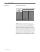
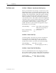
Setup (cont.) RF1 & RF2 Resistor Setup (cont.)
Table 4.A – Feedback Resistor Values • Synchronous Field Feedback Board
Useable Voltage Range
RF1/RF2
Resistance
(K ohm)
Lower Limit Upper Limit
2.5 60 160
5 120 320
7.5 170 480
10 230 640
12.5 290 800
15 350 950
17.5 400 1100
20 460 1300
Note: Resistance value is per resistor (two required).
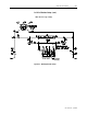
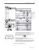
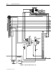
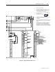
NOTE : Motor induced currents will cause a voltage to be
produced across the synchronous motor starter field discharge
resistor. This voltage is connected to the feedback resistors and
the tap to be selected on these resistors is dependent on this
voltage level. For example, if the discharge resistor value is 20
ohms and the induced currents are 30 amperes at 0 speed and 18
amperes at 95 percent speed, then the induced voltage seen by the
feedback resistors will range from 600 volts (0 speed) to 360 volts
(95% speed). The selection would then be 10 kilohms on each of
the 2 resistors. In the event that the induced voltage proves to be
higher than allowed by the chart, it will be necessary to tap the
field discharge resistor at a point which will allow the value to fall
within the chart. Refer to Rockwell Automation for assistance.