
Owner's manual


Installation
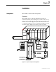
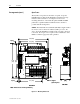
Arrangements The SyncPro is offered in three arrangements.
Component
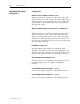
The SyncPro may be ordered as individual components for
maximum flexibility when installing the controller. The user may
then mount the components in a configuration most suitable to his
main motor controller equipment layout. Care must be exercised
to ensure the SyncPro processor has adequate ventilation provided
around it. Refer to Figure 3.6 for wiring of the components.
SyncPro
DTAM
SLC 5/03
CPU
INPUT OUTPUT
INPUT
OUTPUT INPUT
FAST
DC SINK
ANALOG
ISOLATED
RELAY 115 VAC
Analog/Digital
Pulse Converter
Relays
(FCR, etc.)
Controls &
Indicators
To Control Power
Analog/Digital
Pulse Converter
To CT (Phase A)
Resistor (RF)
Resistor (RF)
To Discharge Resistor
To Discharge Resistor
˜
SyncPro
DTAM
SLC 5/03
CPU
INPUT OUTPUT
INPUT
OUTPUT INPUT
FAST
DC SINK
ANALOG
ISOLATED
RELAY 115 VAC
Analog/Digital
Pulse Converter
Relays
(FCR, etc.)
Controls &
Indicators
To Control Power
Analog/Digital
Pulse Converter
To CT (Phase A)
Resistor (RF)
Resistor (RF)
To Discharge Resistor
To Discharge Resistor
˜
Figure 3.1 – SyncPro Component Configuration
Chapter 3
1901-UM020C-EN-P – June 2013