SyncPro™ Bulletin 1901 Installation Manual www.abpowerflex.
Important User Information Read this document and the documents listed in the Additional Resources section about installation, configuration, and operation of this equipment before you install, configure, operate, or maintain this product. Users are required to familiarize themselves with installation and wiring instructions in addition to requirements of all applicable codes, laws, and standards.
Table Of Contents Product Description Chapter 1 Description ............................................................................................. 1-1 Documentation ....................................................................................... 1-1 Synchronous Motor Theory ................................................................... 1-2 Protection Features ................................................................................. 1-3 Theory of Operation .......................
ii Table of Contents – SyncPro™ Instruction Manual Setup and Commissioning Chapter 4 Setup ..................................................................................................... Lithium Battery ............................................................................... Analog Card DIP Switches ............................................................. Programmer/Display DTAM .......................................................... RF1 and RF2 Resistor Setup .......................
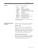
Chapter 1 Product Description Description The SyncPro consists of a programmable small logic controller (SLC 500) with the following additional peripheral items: • • • • • Data Table Access Module (DTAM) Power Factor Transducer Analog/Digital Pulse Board Conditioning Resistors Interposing Relays FCR and ESR The SyncPro system is designed to provide supervisory protection and field control to a brush-type synchronous motor controller, proper field application timing, squirrel-cage protection against lon
1-2 Product Description Synchronous Motor Theory The synchronous motor is a commonly used industrial motor favored for its higher efficiency, superior power factor, and low inrush currents. Typical applications that benefit from the constant operating speed include refiners, head box fan pumps, chippers, etc. Synchronous motors are particularly well suited to low RPM applications. The synchronous brush-type motor is composed of a three-phase stator winding, a DC rotor winding, and a squirrelcage winding.
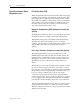
Product Description Protection Features 1-3 Theory of Operation When the NOT STOP and START signals go high, a timer is started (refer to Figure 7.1). The START signal must be dropped before another start can be initiated. The timer is preset based on the slip frequency of the motor. If the timer expires prior to achieving the maximum asynchronous speed, the starting sequence will halt, the TRIP output will be dropped and the DTAM will display a message indicating the faulted condition.
1-4 Product Description Protection Features (cont.) When the maximum programmed percentage of synchronous speed (set point) is obtained, the field coil is energized on the falling pulse of the negative square wave (i.e. a rising sinusoid) from the slip frequency generator. A fixed time period after synchronization, the autoload signal is raised. The field coil is energized only if the TRANSITION COMPLETE has been received.
Product Description Hardware 1-5 The system consists of the following hardware: • • • • • • • • • • • • • • SyncPro 1747-L532 1746-ITB16 1746-NIO4I 1746-0X8 1746-IA16 1746-A7 1746-P1 1747-DTAM 700-F220A1 80165-998-51 80025-817-01 80165-778-51 800T-PB16R 5/03 Processor : EEPROM High Speed DC Input Module Analog Input/Output Module Isolated Relay Output (or any 8-point output) 120VAC Input Module (or any 16-point input) 7-Slot Rack Power Supply Data Table Access Module Interposing Relay (FCR, ESR) Phase
1-6 Product Description Typical Synchronous Starter Components (cont.) Field Voltage Relay (FVR) When energized, this DC relay indicates that the DC exciter supply is healthy and producing an adequate level of DC excitation. The field voltage relay is required to prevent starting the motor unless DC excitation is available. A field voltage relay is recommended as the SyncPro does not have the ability to determine the level of the exciter output voltage.
Product Description 1-7 Discharge Resistor The discharge resistor is specified by the motor manufacturer for a specific application to obtain correct starting and pull in torques and to provide a means of discharging the motor induced field voltage when starting and stopping the motor. The field winding has more turns than the stator winding and when power is applied to the stator, the field acts like the secondary windings of a current transformer.
1-8 Product Description Input/Output Descriptive Listing Control NOT STOP (I:4/00) This signal must be maintained high for the SyncPro to operate. When the signal is taken low, the software identifies this as a normal stop for the motor. Important: The SyncPro does NOT have control over stopping the motor. The main portion of the motor controller performs this control function. The NOT STOP signal must be given in parallel to that of the hardware, i.e. from the same PLC output or push button.
Product Description 1-9 Field Application TRANSITION COMPLETE CONTACT (I:4/06) (OPTIONAL) The field relay output will not be energized until this input permissive is given. Once the field relay is picked up, this permissive is no longer required. If the permissive is not given prior to the squirrel-cage protection timing out or the incomplete sequence timing out, the SyncPro will fault and stop the motor. If unused, it must be tied high.
1-10 Product Description Input/Output Descriptive Listing (cont.) Fault Detection FIELD VOLTAGE RELAY INPUT (I:4/03) When the signal is low, it indicates a lack of field voltage. This input is monitored for a fault condition only while starting, prior to applying the field. Tie this input high if it is not used. When this contact is high, it verifies that the static exciter is providing an appropriate DC voltage.
Product Description 1-11 Status AUTO LOAD (O:3/07) Output is energized two seconds after the field is applied and remains closed until the field is removed from the motor by a stop or a fault. SCP TRIP (O:3/02) Output is set high when a Squirrel-Cage Protection Fault occurs. It is reset when the TRIP output goes high after pushing the reset button. This signal can be used for indication, via a pilot light, or it can be used as an optional trip output.
1-12 Product Description Specifications (cont.) Specific Specifications (for Phase Angle Transducer) General Accuracy: Housing: Weight: 3% span Flame retardant plastic case 2.4 kg maximum Climate Storage: Temp. range: Humidity: -20 to 70°C (-4 to 158°F) -20 to 70°C (-4 to 158°F) storage Operational @ 0 to 60°C (32 to 140°F) Calibrated @ 23°C (73°F) Up to 95% RH. Non-condensing Input Frequency: Current: Range (A): Burden: Voltage: Range (V): 50 or 60 Hz Any value between 0.
Chapter 2 Receiving and Storage Receiving Upon receiving the controller, remove the packing and check for damage that may have occurred during shipping. Report any damage immediately to the claims office of the carrier. NOTE: If the SyncPro is an integral component of a brush-type synchronous starter (Bulletin 1912B), special receiving and handling instructions will apply. For details, refer to the service manual provided with the equipment.
2-2 Receiving and Storage 1901-UM020C-EN-P – June 2013
Chapter 3 Installation Arrangements The SyncPro is offered in three arrangements. Component The SyncPro may be ordered as individual components for maximum flexibility when installing the controller. The user may then mount the components in a configuration most suitable to his main motor controller equipment layout. Care must be exercised to ensure the SyncPro processor has adequate ventilation provided around it. Refer to Figure 3.6 for wiring of the components.
Installation 3-2 Arrangements (cont.) Open Frame The SyncPro components are mounted on a panel, except the DTAM display module and the illuminated push button for trip indication and reset function. See Figures 3.2 and 3.3 for mounting dimensions of the main unit panel, DTAM and 800T push button. Quick installation within the main controller is possible with this arrangement. NOTE: The Data Table Access Module (DTAM) is supplied with a two-meter cord for connection with the SyncPro processor.
Installation 3-3 Open Frame (cont.) Analog/Digital Pulse Converter Board Fusible Terminal Blocks Conditioning Resistors, RF Terminal Blocks FCR Relay (DIN Rail Mounted) ESR Relay (DIN Rail Mounted) Phase Angle Transducer (DIN Rail Mounted) Bulletin 1746 7-slot Card Rack with P1 Power Supply Ground Bar Figure 3.
3-4 Installation Wiring Guidelines The SyncPro™ can accept either two- or three-wire control. The control chosen will determine the configuration of the control hardware. Consider the following two inputs and single output when selecting the type of control: • I:4/00 • I:4/01 • O:3/06 NOT STOP input START input RUN output If using two-wire control, the two inputs (I:4/00 and I:4/01) are tied together.
Installation 3-5 In both cases, the RUN output will follow the state of the START input, provided that all starting conditions are met. Note that in all cases, stopping the motor is done via the hardwired control circuit logic, and notification only is given to the SyncPro™. Figure 3.4 shows a typical two-wire control circuit. The selector switch is used to control the NOT STOP and the START as a pair.
3-6 Installation Wiring Guidelines (cont.) E-STOP O/L External O:3/01 TRIP ESR Equipment Shutdown Relay I:4/07 EQUIP SHUTDOWN PB START I:4/01 START PB STOP I:4/00 NOT STOP ESR O:3/06 RUN CR Main Contactor Pilot Relay FCR Field Coil Relay (Pilot Relay) CR O:3/00 FIELD RLY FCR * I:4/05 FLD CONT AUX * Auxiliary Contact from final coil in chain (if acceptable) I:4/06 TRANS CMP Eg. Not Used MC I:4/08 M CONT FDBK I:4/04 FLD CURRENT RLY FVR I:4/03 FVR RELAY PB RESET I:4/02 RESET Figure 3.
Installation 3-7 In this case (three-wire) since the START signal is only momentary, the hardware must perform the sealing function using the control relay, CR. The START output is really an extension of the START input, except that the output is conditioned by any fault conditions. The ESR circuit ensures the motor is stopped for any fault condition occurring either externally or when detected by the SyncPro.
3-8 Installation ○ ○ ○ ○ ○ ○ ○ ○ ○ ○ ○ ○ ○ ○ ○ ○ ○ ○ ○ ○ ○ ○ ○ ○ ○ ○ ○ ○ ○ ○ ○ ○ ○ ○ ○ Wiring Guidelines (cont.) ○ ○ Figure 3.
Chapter 4 Set up and Commissioning Setup Check the following components of the SyncPro once it has been installed. Lithium Battery Ensure the supplied lithium battery is connected. This battery maintains power to the processor, preserving programmed set points loaded into RAM memory through the DTAM. To verify the connection, remove the processor in slot 0 of the I/O rack. The battery is on the printed circuit board with wires extending from it to a keyed connector.
4-2 Setup and Commissioning Setup (cont.) Programmer/Display DTAM (cont.) The DTAM will now re-attach to the SyncPro 5/03. The F()-1 and F()-2 Macros must now be programmed into the DTAM.
4-3 Setup and Commissioning RF1 & RF2 Resistor Setup (cont.) These settings must be made prior to any start attempt. Determining the induced voltage which will appear across the discharge resistor during starting can be done two ways: a) If motor data is available the voltage can be determined by multiplying the discharge resistance by the induced currents at zero and 95% speed as given by the motor manufacturer i.e. induced current @ 0 % speed – 20 Amps. induced current @ 95% speed – 12 Amps.
4-4 Setup and Commissioning Setup (cont.) RF1 & RF2 Resistor Setup (cont.) Procedure for Selection of Resistors Discharge resistance Sample resistance – – ___________ ___________ ohms ohms 0 % speed peak to peak voltage 95% speed peak to peak voltage – – ___________ ___________ V (Vpeak@0) V (Vpeak@95) Induced voltage (0 % speed) Induced voltage (95% speed) – – ___________ ___________ V (Vrms@0) Vp0/2.828 V (Vrms@95) Vp95/2.
Setup and Commissioning 4-5 RF1 & RF2 Resistor Setup (cont.) “RF” Resistor tap settings To SLC, Slot 1 To SLC 24V DC Power Supply Figure 4.
4-6 Setup and Commissioning Setup (cont.) RF1 & RF2 Resistor Setup (cont.) Table 4.A – Feedback Resistor Values • Synchronous Field Feedback Board RF1/RF2 Resistance (K ohm) Lower Limit Upper Limit 2.5 60 160 5 120 320 7.5 170 480 10 230 640 12.5 290 800 Useable Voltage Range 15 350 950 17.5 400 1100 20 460 1300 Note: Resistance value is per resistor (two required).
Setup and Commissioning Commissioning 4-7 1. Complete and verify that the setup procedures (pages 4-1 to 4-6) have been completed. This should include verifying that the parameters programmed into the SyncPro are appropriate for the motor. See Chapter 5 for further details on programming. 2. Verify that the SyncPro has been wired into the motor starter circuit as indicated by the wiring diagram. 3.
4-8 Setup and Commissioning Commissioning (cont.) NOTE: The phase angle transducer, as wired from the factory, is set up for the customer to run his wiring with an ABC line orientation. If this was not observed, the user has two options. First, the line cables can be moved (switching any two incoming lines will do) so that ABC now exists (BCA or CAB are also acceptable), OR the current transformer leads to the transducer can be swapped at the transducer. 5.
Setup and Commissioning 4-9 CPT H1 H2 X1 X2 L MT F3 1 4.
Setup and Commissioning 4-10 ANALOG/DIGITAL BOARD TB1 TB2 C BLK R W BLK L G N F2 P F1 RF1 20 kOHM RF2 20 kOHM C V 1 F3 1 1 2 3 4 5 5 6 6 7 7 8 9 9 10 10 12 12 C3A C3A C3B C3B 20 20 1 26 27 28 31 29 30 SLOT 1 24 VDC Input 1746-IB16 31 32 33 34 IN 0 35 36 IN 1 37 IN 2 SLOT 0 5/03 CPU 1746-P1 BLK (Remove Jumper If present) 24VDC C 12 GROUND BAR 5 IN 3 IN 4 W COM 1 W R POWER SUPPLY 5 BLK R IN 5 + 120VAC Battery MOV VAC NEUT - GRD IN 6 IN 7 IN 8 #14 WIR
Setup and Commissioning 4-11 M Customer supplied equipment. N FLR and TC are optional customer supplied inputs which are jumpered to terminal blocks, if not used. O Contact rating is 60 amp Make, 10 amp Break (inductive) – 10 amp continuous at 120 V AC (A600). P Refer to instruction manual for tap selection guidelines on RF1 and RF2 resistors. Q Analog card switch settings are: R Customer to take ground wire to ground bus (earth ground).
4-12 Setup and Commissioning 1901-UM020C-EN-P – June 2013
Chapter 5 Programming the SyncPro Set Points Prior to use, the Synchronous Protector must be programmed with nine common set points and possibly one additonal parameter. To start the programming procedure a macro has been defined in the DTAM as F()-1. Press [ESC], then the [F()] key followed by the [1] key. The register N23:0 will be displayed. Enter a value of 1 and press [ENTER] to start the sequence. During the sequence, the following set points are entered: 1. 2. 3. 4. 5. 6. 7. 8. 9.
5-2 Programming Set Points (cont.) Set Point 1 • Minimum % Synchronous Slip Frequency This set point determines the percentage of synchronous speed at which the DC voltage is to be applied by the field contactor. The SyncPro monitors the frequency of the induced voltage across the discharge resistor during starting. When this frequency indicates that the motor has achieved the desired subsynchronous speed at which it is allowable to synchronize, the SyncPro energizes the coil of the field contactor.
Programming 5-3 Set Point 4 • Squirrel-Cage Protection Trip Time (at 95% speed) This time setting determines the maximum length of time the synchronous motor may run at 95% speed before it is shut down. The squirrel-cage winding of the synchronous motor is not rated to run the motor continuously even at no load and therefore must be shut down if synchronism does not occur. Time should be set to motor manufacturer's specifications.
5-4 Programming 1901-UM020C-EN-P – June 2013
Programming 5-5 Set Point 8 • Incomplete Sequence Trip Time Delay Once a synchronous starter has been commissioned, the acceleration and synchronization times should remain fairly consistent provided that the starting load does not vary significantly. The incomplete sequence timer can be set to a time delay that is slightly higher than the slowest acceleration time. The aforementioned squirrel-cage protection features protect the motor, but they also let it go to its thermal limitations.
5-6 Programming Additional Parameters System Frequency The SyncPro can function on either 50 or 60 Hz power systems. The unit as standard is shipped to operate at 60 Hz. The unit may be changed to operate at 50 Hz by entering a value of 50 in integer word N23:1. To change back to 60 Hz, a value of 60 can be reentered. To access word N23:1, press [ESC], then the [F()] key followed by the [2] key. The register will be displayed. Enter the desired value and press [ENTER].
Chapter 6 Monitoring Power Factor Power in DC circuits is the product of voltage and amperes, thus: W (watts) = E x I However, in AC power circuits some period of time in each cycle may have voltage and current of opposing sign (positive or negative) and their product will be negative, denoting negative power. This must be subtracted from the positive power for each cycle to yield the net power.
6-2 Monitoring Faults (cont.) Fault Detection and Diagnostics (cont.) Upon starting the motor, additional diagnostics are performed. Any of these conditions will abort the start. Diagnostics performed are: a) Lack of either pulse signal from the slip frequency generator. b) Lack of field voltage or field current (if applicable). c) Power Factor Transducer Circuit Fault.
Chapter 7 Troubleshooting Last Trip Table To aid in troubleshooting, the unit stores the last 10 recorded faults. These can be accessed by viewing the contents of the data file N22:0, (refer to the DTAM manual 1747-ND013 for information on data table access). This file forms a circular queue from N22:1 to N22:10 such that when full, the oldest fault is discarded making room for the newest. The value in N22:0 gives the most recent fault. For example: N22:0 has the value of 6.
7-2 Troubleshooting Table 7.B – Troubleshooting Guide Problem or Trip indicated Pullout trip (power factor) [POWER FACTOR TRIP] Squirrel-cage Protection Trip [SQ.
Troubleshooting 7-3 Table 7.B – Troubleshooting Guide (cont.) Problem or Trip indicated Indication of the following conditions Possible Solutions Pulse Board Positive and Negative Pulse Missing [PULSE BOARD +’VE] [PULSE BOARD –‘VE] • The SyncPro is not seeing a pulse train being supplied from the A/D board at the time of starting. Contactor Feedback Lost [MOTOR CONT. FDBK] • The SyncPro monitors the status of the synchronous motor stator contactor while running.
7-4 Troubleshooting 1901-UM020C-EN-P – June 2013
Chapter 8 Spare Parts SyncPro Spare Parts List Table 8A – Spare Parts List Part Number 1746-IA16 1746-ITB16 1746-NIO4I 1746-OX8 1746-P1 1746-F1 1747-L532 1747-BA 1747-DTAM-E 1747-C10 1747-C20 800T-PB16R 800T-N65 800T-N40 700-F220A1 X-251089 80165-778-51-R 80025-817-01-R 700DC-P200Z1 700DC-P200Z2 80190-020-01-R 80190-020-02-R Designation 1746-IA16 1746-ITB16 1746-NIO4I 1746-OX8 1746-P1 — SLC 5/03 CPU — 1747-DTAM-E 1747-C10 1747-C20 Trip/Reset FCR, ESR F3 — 20 kilohms tapped FVR 120 V 240 V Description
8-2 Spare Parts 1901-UM020C-EN-P – June 2013
Medium Voltage Products, 135 Dundas Street, Cambridge, ON, N1R 5X1 Canada, Tel: (1) 519.740.4100, Fax: (1) 519.623.8930, www.ab.com/mvb Publication 1901-UM020&-EN-P – -XQH Supersedes Publication 1901-80 % (1 3 – $SULO Copyright © 20 Rockwell Automation. All rights reserved. Printed in Canada.