Installation Instructions 16 Input/16 Output Digital and 2 Input/2 Output Analog Embedded I/O Boards Catalog Numbers 1799-D16U16VAGL, 1799-D16U16BAGL Topic Page Important User Information 2 Environment and Enclosure 3 About the Board 3 Install the Board 4 Set the Node Address 5 Mount the Board 6 Connect the Board 8 Configure the Parameters 17 Calibrate Your Analog Inputs and Outputs 19 Troubleshoot the I/O Boards 26 Specifications 28 About This Publication This publication provide
16 Input/16 Output Digital and 2 Input/2 Output Analog Embedded I/O Boards Important User Information Solid state equipment has operational characteristics differing from those of electromechanical equipment. Safety Guidelines for the Application, Installation and Maintenance of Solid State Controls (Publication SGI-1.1 available from your local Rockwell Automation sales office or online at http://www.literature.rockwellautomation.
16 Input/16 Output Digital and 2 Input/2 Output Analog Embedded I/O Boards 3 Environment and Enclosure ATTENTION This equipment is intended for use in a Pollution Degree 2 industrial environment, in overvoltage Category II applications (as defined in IEC publication 60664-1), at altitudes up to 2000 m (6562 ft.) without derating. This equipment is considered Group 1, Class A industrial equipment according to IEC/CISPR Publication 11.
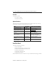
16 Input/16 Output Digital and 2 Input/2 Output Analog Embedded I/O Boards Parts List Your package contains: • one 1799 I/O board. • installation instructions. Optional Hardware All mating connectors and mounting hardware must be ordered separately. The following table identifies the different connector and hardware options.
16 Input/16 Output Digital and 2 Input/2 Output Analog Embedded I/O Boards ATTENTION 5 Prevent Electrostatic Discharge This equipment is sensitive to electrostatic discharge, which can cause internal damage and affect normal operation. Follow these guidelines when you handle this equipment: • • • • • • Touch a grounded object to discharge potential static. Wear an approved grounding wriststrap. Do not touch connectors or pins on component boards. Do not touch circuit components inside the equipment.
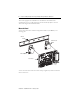
16 Input/16 Output Digital and 2 Input/2 Output Analog Embedded I/O Boards The board is equipped with AutoBaud detect. AutoBaud lets the board detect the communication rate on your DeviceNet network and automatically adjusts to that rate. The board is shipped with AutoBaud enabled. Mount the Board You can mount the board to a DIN rail using DIN-rail brackets (1799-BRKD) or to a mounting plate.
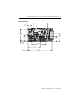
16 Input/16 Output Digital and 2 Input/2 Output Analog Embedded I/O Boards 7 Board Dimensions 29.21 (1.15) 88.90 (3.50) 44.45 (1.75) 41.66 (1.64) 6.35 (0.25) 60.71 (2.39) 109.22 (4.30) 87.63 (3.45) 6.35 (0.25) 175.26 (6.
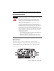
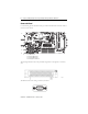
16 Input/16 Output Digital and 2 Input/2 Output Analog Embedded I/O Boards Connect the Board Use the following pictures and tables to help you connect the DeviceNet connectors and I/O connectors to the board. P1 P5 P8 P7 P6 P1 = DeviceNet Connector P5 = I/O Connector P6 = Analog I/O Connector P7 = Analog I/O Connector P8 = Analog Power Connector 42561A The following illustration shows the pin number assignments of the digital I/O connector (P5).
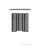
16 Input/16 Output Digital and 2 Input/2 Output Analog Embedded I/O Boards 9 The following table identifies the signal for each 1799-D16U16BAGL pin number on the I/O connector.
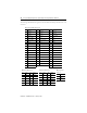
16 Input/16 Output Digital and 2 Input/2 Output Analog Embedded I/O Boards The following table identifies the signal for each 1799-D16U16VAGL pin number on the I/O connector.
16 Input/16 Output Digital and 2 Input/2 Output Analog Embedded I/O Boards 11 The DeviceNet wire insulation colors are shown below.
16 Input/16 Output Digital and 2 Input/2 Output Analog Embedded I/O Boards Connect the Field Output Device to the I/O Connector (P5) The 1799-D16U16BAGL boards have outputs that supply current to your field output device (sourcing outputs). The outputs on these boards are isolated in two groups of eight, with each group requiring 24V dc power and 24V dc ground. Outputs 0…7 are powered from +24V GRP 0 and return power via GRP 0 Return.
16 Input/16 Output Digital and 2 Input/2 Output Analog Embedded I/O Boards 13 Connect the Field Input Device to the I/O Connector (P5) The inputs on these boards are isolated in two groups of eight, with each group providing a separate common signal. Inputs 0…7 share the common in GRP 0 signal. Inputs 8…15 share the common in GRP 1 signal. The 1799-D16U16BAGL and 1799-D16U16VAGL boards have universal inputs that allow operation with either sourcing or sinking input devices.
16 Input/16 Output Digital and 2 Input/2 Output Analog Embedded I/O Boards Communicate With Your Board This board exchanges I/O with the master on the DeviceNet network through a cyclic, polled, or change-of-state connection. The 1799-D16U16BAGL board consumes and produces I/O data as follows. I/O Connection Type Consumes Produces Cyclic 6 Bytes 11 Bytes Polled 6 Bytes 11 Bytes Change-of-state 6 Bytes 11 Bytes The 1799-D16U16VAGL board consumes and produces I/O data as follows.
16 Input/16 Output Digital and 2 Input/2 Output Analog Embedded I/O Boards 15 Word and bit definitions for the 1799-D16U16BAGL board are shown below.
16 Input/16 Output Digital and 2 Input/2 Output Analog Embedded I/O Boards Word and bit definitions for the 1799-D16U16VAGL board are shown below.
16 Input/16 Output Digital and 2 Input/2 Output Analog Embedded I/O Boards 17 Configure the Parameters The 1799 I/O boards have parameters that are configurable through a DeviceNet configuration tool such as RSNetWorx for DeviceNet software. The DeviceNet configuration tools require an Electronic Data Sheet (EDS) for the 1799 I/O boards to configure the module’s parameters. Find the EDS files at http://www.odva.org. Use the descriptions in the following table to help you configure the parameters.
16 Input/16 Output Digital and 2 Input/2 Output Analog Embedded I/O Boards Additional Parameters Parameter Description AI Low Scaling Analog input low scaling value or low engineering units. AI High Scaling Analog input high scaling value or high engineering units. AI Digital Filter Controls digital filter time constant. AI Alarm (Low/High Low) Low/High High) Control alarm status when input exceed alarm threshold. AI Input Range Defines type and range of input signal.
16 Input/16 Output Digital and 2 Input/2 Output Analog Embedded I/O Boards 19 Calibrate Your Analog Inputs and Outputs Follow the example calibrations shown below to learn how to calibrate your card. Input Calibration The wiring method decides the operating mode of current or voltage inputs. Calibration data of both voltage and current are stored in nonvolatile memory and selected according to the parameter value of AI INPUT RANGE.
16 Input/16 Output Digital and 2 Input/2 Output Analog Embedded I/O Boards 4. Apply 4.000 mA ±0.5 μA and allow to settle for a minimum of 200 ms. TIP Always apply 4 mA to inputs as low reference when calibrating current inputs. 5. Send the Accept Low Calibration command. 6. Apply 20.00 mA ( ±0.5 μA) and allow to settle for a minimum of 200 ms. 7. Send the Accept High Calibration command. 8.
16 Input/16 Output Digital and 2 Input/2 Output Analog Embedded I/O Boards 21 Example voltage calibration of channel 0 1. Set input channel range 0…10V. 2. Select the input channel. 3. Send command to Begin Calibration. 4. Apply 0.000V (±) 500 μV and allow to settle for a minimum of 200 ms. 5. Send the Accept Low Calibration command.
16 Input/16 Output Digital and 2 Input/2 Output Analog Embedded I/O Boards 6. Apply 10.000V (±500 μV) and allow to settle for a minimum of 200 ms. 7. Send the Accept High Calibration command. 8. If both samples were successful the module saves data to Dataflash, recalculates module parameters and exits calibration automatically. Calibration can be aborted or restarted at any time. Data is not saved until the end of step 7.
16 Input/16 Output Digital and 2 Input/2 Output Analog Embedded I/O Boards 23 3. Apply a 220 Ω (±15%) load resistor to channel 0. 4. Send Begin Calibration command. 5. Send the Output Low Reference command 6. Record the actual output current. 7. Send the Output High Reference command. 8. Record the actual output current. 9. Set parameter values with recorded values.
16 Input/16 Output Digital and 2 Input/2 Output Analog Embedded I/O Boards 10. Send the Finish Calibration command. 11. If LED indicators are no longer blinking, calibration is complete. Calibration can be aborted or restarted at any time. Data is not saved until the end of step 10. Example voltage calibration of channel 0. 1. Set output channel range to 0…10V. 2. Select output channel 0. 3. Apply a 10 KΩ (± 1%) load resistor to channel 0. (10V output/10 K = 1 mA load) 4.
16 Input/16 Output Digital and 2 Input/2 Output Analog Embedded I/O Boards 25 5. Send the Output Low Reference command 6. Record the actual output current. 7. Send the Output High Reference command. 8. Record the actual output voltage. 9. Set parameter values with recorded values. 10. Send the Finish Calibration command. 11. If LED indicators are no longer blinking calibration is complete. Calibration can be aborted or restarted at any time. Data is not saved until the end of step 10.
16 Input/16 Output Digital and 2 Input/2 Output Analog Embedded I/O Boards Troubleshoot the I/O Boards This board has the following indicators: • • • • • Board status indicator Network status indicator Logic status Digital I/O state indicators Analog I/O state indicators Status Indicators Input LEDs DL NS MS Analog LEDs Output LEDs LSD P1 MSD P5 P8 P7 P6 42567A Board Status Indicator (Labeled MS) Indication Green Red Status None No power Blinking Green Needs commissioning Solid Gree
16 Input/16 Output Digital and 2 Input/2 Output Analog Embedded I/O Boards 27 Network Status Indicator (Labeled NS) Indication Green Red Status None Not on-line Blinking Green On-line/no connections Solid Green On-line/connected Blinking Red Connection timed out Solid Red Failed communication: a duplicate node address exists or module is at the wrong communication rate DeviceLogix Status Indicator (Labeled DL) Indication Green Status None Logic disabled Solid Green Logic enabled Blinking G
16 Input/16 Output Digital and 2 Input/2 Output Analog Embedded I/O Boards Specifications 16 Input/16 Output Board - Cat. No.
16 Input/16 Output Digital and 2 Input/2 Output Analog Embedded I/O Boards 29 Analog input specifications Voltage, power 10…28.8V Input current range 0…21 mA Input resolution 0.32 μA/count (16 bits) Input voltage range 0…10.5V max; 21 mA max Current input impedance 238 Ω Voltage input impedance 190 kΩ Accuracy current voltage 0.012% of FS 0.007% of FS Analog output specifications Output current range 0…21.5 mA Output voltage range 0…10.5V Output resolution - current 2.
16 Input/16 Output Digital and 2 Input/2 Output Analog Embedded I/O Boards Enclosure type rating None (open-style) Pilot Duty Rating Pilot duty DC-14 LED indicators Board Status indicator - red/green Network Status indicator - red/green DeviceLogix Status indicator - green Input Point indicator - yellow Output Point indicator - yellow Dimensions (H x W x D), approx. millimeters (inches) 19.05 x 77.85 x 189.33 mm (0.75 x 3.07 x 7.45 in.) Weight 0.10 kg (0.
16 Input/16 Output Digital and 2 Input/2 Output Analog Embedded I/O Boards EFT/B immunity IEC 61000-4-4 ±2 kV at 5 kHz on power ports ±2 kV at 5 kHz on signal ports ±2 kV at 5 kHz on communications ports Surge transient immunity IEC 61000-4-5: ±1 kV line-line (DM) and ±2 kV line-earth (CM) on power ports ±1 kV line-line (DM) and ±2 kV line-earth (CM) on signal ports ±2 kV line-earth (CM) on communications ports Conducted RF immunity IEC 61000-4-6: 10V rms with 1 kHz sine-wave 80%AM from 150 kHz...
Rockwell Automation Support Rockwell Automation provides technical information on the Web to assist you in using its products. At http://support.rockwellautomation.com, you can find technical manuals, a knowledge base of FAQs, technical and application notes, sample code and links to software service packs, and a MySupport feature that you can customize to make the best use of these tools.