Installation Instructions 12 Input/12 Output Discrete Embedded TTL I/O Module with Pulse Width Modulation and DeviceLogix Cat. No. 1799-D12G12GL Inside...
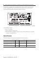
12 Input/12 Output Discrete Embedded TTL I/O Module with Pulse Width Modulation and DeviceLogix The module is equipped with AutoBaud detect, and is shipped with Autobaud enabled. AutoBaud lets the module detect the baud rate on your DeviceNet network and automatically adjusts the module to that rate.
12 Input/12 Output Discrete Embedded TTL I/O Module with Pulse Width Modulation and DeviceLogix Important User Information Solid state equipment has operational characteristics differing from those of electromechanical equipment. Safety Guidelines for the Application, Installation and Maintenance of Solid State Controls (Publication SGI-1.1 available from your local Rockwell Automation sales office or online at http://literature.rockwellautomation.
12 Input/12 Output Discrete Embedded TTL I/O Module with Pulse Width Modulation and DeviceLogix ATTENTION Environment and Enclosure This equipment is intended for use in a Pollution Degree 2 industrial environment, in overvoltage Category II applications (as defined in IEC publication 60664-1), at altitudes up to 2000 meters without derating. This equipment is considered Group 1, Class A industrial equipment according to IEC/CISPR Publication 11.
12 Input/12 Output Discrete Embedded TTL I/O Module with Pulse Width Modulation and DeviceLogix ATTENTION Prevent Electrostatic Discharge This equipment is sensitive to electrostatic discharge, which can cause internal damage and affect normal operation. Follow these guidelines when you handle this equipment: • • • • • • Touch a grounded object to discharge potential static. Wear an approved grounding wriststrap. Do not touch connectors or pins on component boards.
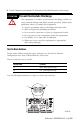
12 Input/12 Output Discrete Embedded TTL I/O Module with Pulse Width Modulation and DeviceLogix Valid node addresses are 00 through 63. Each board is shipped with the node address set to 63 in the board’s memory. The rotary switches are set for position 99 at shipment. TIP The rotary switches are read at board power-up only. Settings between 64 and 99 cause the board to use the last valid node address stored in the board’s memory. To set the node address, do the following: 1.
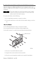
12 Input/12 Output Discrete Embedded TTL I/O Module with Pulse Width Modulation and DeviceLogix Module Dimensions 8.9 cm 3.5 in. 7.9 cm 3.125 in. 7.8 cm 3.0625 in. 7.8 cm 3.0625 in. 31580-M 16.5 cm 6.5 in. Connect the Module Use the following illustrations and tables to help you connect the DeviceNet and I/O connectors to the module. DeviceNet Connector (P1) P5 P4 P3 P2 31571-M ATTENTION I/O cabling must be less than 6 m (19.7 ft).
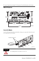
12 Input/12 Output Discrete Embedded TTL I/O Module with Pulse Width Modulation and DeviceLogix TIP If necessary to guard against excessive vibration, tighten the two screws on the DeviceNet connector (P1) to a maximum torque of 0.79 N-m (7 in-lbs). I/O Connector Pin Assignments The following illustration depicts the pin number assignments of the I/O connectors (P2 through P5).
12 Input/12 Output Discrete Embedded TTL I/O Module with Pulse Width Modulation and DeviceLogix I/O Connector Inputs and Outputs The following table identifies the inputs and outputs for connectors P2 through P5.
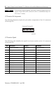
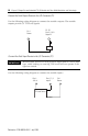
12 Input/12 Output Discrete Embedded TTL I/O Module with Pulse Width Modulation and DeviceLogix Connect the Field Output Device to the I/O Connector (P1) Use the following wiring diagram to connect the module outputs. The module outputs provide 5V TTL level signals. P2 - P5 Pins 3, 5, 6, 8 Output X Pin 1 Return Load Connect the Field Input Device to the I/O Connector (P1) IMPORTANT All field input devices in each group of eight must be of the same type, either sinking or sourcing.
12 Input/12 Output Discrete Embedded TTL I/O Module with Pulse Width Modulation and DeviceLogix Communicate with the Module The module exchanges I/O data with the master on DeviceNet through cyclic, polled, or change-of-state messaging. Messaging Type Description Cyclic The module produces and consumes I/O data cyclically at the rate configured by the master on the DeviceNet network. Polled The master initiates communication by sending its polled I/O message to the board.
12 Input/12 Output Discrete Embedded TTL I/O Module with Pulse Width Modulation and DeviceLogix Refer to the following table for the word/bit definitions for the 1799-12G12GL boards Byte Bit 7 Bit 6 Bit 5 Bit 4 Bit 3 Bit 2 Bit 1 Bit 0 Produced 0 I7 I6 I5 I4 I3 I2 I1 I0 Produced 1 Reserved Logic Enabled Reserved Reserved I11 I10 I9 I8 Produced 2 O7 O6 PWM Enabled 1 05 04 O3 O2 PWM Enabled 0 O1 O0 Produced 3 O15 O14 PWM Enabled 3 O13 O12 O11 O10 PWM Enabled 2 09 O8 N
12 Input/12 Output Discrete Embedded TTL I/O Module with Pulse Width Modulation and DeviceLogix Parameter Description Output Fault Value Controls the value that outputs will have when the output fault state is set to ‘use fault value.’ Consumed I/O Assembly Lets you select size of consumed data. Network Status Override Lets local logic override output behavior when the module is not online.
12 Input/12 Output Discrete Embedded TTL I/O Module with Pulse Width Modulation and DeviceLogix Parameter Selection Available Status Bits Explicit Message Connection Polled Connection Change-of-State/Cyclic Connection Change-of-State/Cyclic Fault Network Fault Minor Module Fault Logic Status Indicators None Solid Green Flashing Green Logic Disabled Logic Enabled Local Forces Applied and Logic Enabled Consumed I/O Assembly The amount of data the module consumes over the DeviceNet network (0 - 4 by
12 Input/12 Output Discrete Embedded TTL I/O Module with Pulse Width Modulation and DeviceLogix Troubleshoot with the Indicators These module indicators are shown below.
12 Input/12 Output Discrete Embedded TTL I/O Module with Pulse Width Modulation and DeviceLogix Board Status Indicator (MOD) Indication Status None No power Green Blinking Solid Needs commissioning Device operational Red Blinking Solid Minor fault Critical fault Network Status Indicator (NET) Indication Status None Not on line • Device has not completed duplicate MAC ID test yet • Device may not be powered yet Green Blinking Solid Red Blinking Solid On line/connected (Group 2 device only) t
12 Input/12 Output Discrete Embedded TTL I/O Module with Pulse Width Modulation and DeviceLogix Inputs and Outputs Status Indicators Indication Status None No power Input or output point off Yellow Input or output point on +5V dc Supply Power Indicator Indication Status Green 5V I/O power None No power Publication 1799-IN008A-EN-P - July 2005
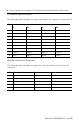
12 Input/12 Output Discrete Embedded TTL I/O Module with Pulse Width Modulation and DeviceLogix Specifications Input Specifications Maximum Minimum Inputs per block 12 TTL compatible Off-State Voltage Current 0.8V dc 0.6 mA - On-State Voltage Current 5.1V dc 10 µA 2.4V dc 0 µA Output Specifications Outputs Per Block Output Auxiliary Voltage Current 12 TTL, 24 mA 5V supply, 5.1V 4.
12 Input/12 Output Discrete Embedded TTL I/O Module with Pulse Width Modulation and DeviceLogix General Specifications (continued) LED Indicators Board Status - red/green Network Status - red/green DeviceLogix Status - green Input Point LED - yellow Output Point LED - yellow 5V I/O supply - green Approximate Dimensions Millimeters (Inches) 165.1 mm x 88.9 mm x 3.53 mm (6.5 in. x 3.5 in. x 0.14 in.
12 Input/12 Output Discrete Embedded TTL I/O Module with Pulse Width Modulation and DeviceLogix General Specifications (continued) EFT/B Immunity IEC 61000-4-4: ±2kV at 2.5kHz on signal ports ±2kV at 5kHz on communications ports Surge Transient Immunity IEC 61000-4-5: ±2kV line-earth (CM) on communications ports Conducted RF Immunity IEC 61000-4-6: 10Vrms with 1kHz sine-wave 80%AM from 150kHz...80MHz Enclosure Type Rating None (open-style) 5V Supply Voltage Ranges 4.8...5.1V 0...5.
12 Input/12 Output Discrete Embedded TTL I/O Module with Pulse Width Modulation and DeviceLogix Certifications Certifications:1 (when product is marked) c-UR-us CE C-Tick ODVA UL Recognized Component Industrial Control Equipment, certified for US and Canada European Union 89/336/EEC EMC Directive, compliant with: EN 50082-2; Industrial Immunity EN 61326; Meas./Control/Lab.
12 Input/12 Output Discrete Embedded TTL I/O Module with Pulse Width Modulation and DeviceLogix Notes: Publication 1799-IN008A-EN-P - July 2005
12 Input/12 Output Discrete Embedded TTL I/O Module with Pulse Width Modulation and DeviceLogix Notes: Publication 1799-IN008A-EN-P - July 2005
Rockwell Automation Support Rockwell Automation provides technical information on the web to assist you in using its products. At http://support.rockwellautomation.com, you can find technical manuals, a knowledge base of FAQs, technical and application notes, sample code and links to software service packs, and a MySupport feature that you can customize to make the best use of these tools.