Installation Instructions FLEX Ex Terminal Base Units Catalog Numbers 1797-TB3 and 1797-TB3S Contents For Information About See Page Important User Information 2 Description 2 Installation in Zone 1 5 Installation in Zone 22 5 Electrostatic Charge 6 European Community Directive Compliance 6 Inputs and Outputs 7 Wire the Terminal Base Units 8 Mount on a DIN Rail 10 Mounting Dimensions 13 About the Mounting Kit 15 Repair 15 Specifications - 1797-TB3 and 1797-TB3S Terminal Base Units
FLEX Ex Terminal Base Units Important User Information Solid state equipment has operational characteristics differing from those of electromechanical equipment. Safety Guidelines for the Application, Installation and Maintenance of Solid State Controls (Publication SGI-1.1 available from your local Rockwell Automation sales office or online at http://www.literature.rockwellautomation.com) describes some important differences between solid state equipment and hard-wired electromechanical devices.
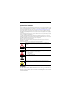
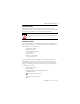
FLEX Ex Terminal Base Units 3 Both terminal bases are equipped with a factory-installed tab cover for the backplane bus connection. The tab cover may be removed only when the terminal base is connected to other terminal bases. 1797-TB3 Screw-cage Terminal Base 11 Only remove this cover plug if connecting another terminal base.
FLEX Ex Terminal Base Units ATTENTION This equipment is considered Group 1, Class A industrial equipment according to IEC/CISPR Publication 11. Without appropriate precautions, there may be potential difficulties ensuring electromagnetic compatibility in other environments due to conducted as well as radiated disturbance. This equipment is supplied as open-type equipment.
FLEX Ex Terminal Base Units 5 Installation in Zone 1 The terminal bases must not be exposed to the environment. Provide a suitable metal enclosure. The terminal bases have a protection factor of IP20. Do not remove the flexbus cover on the rightmost terminal base. WARNING The terminal bases cannot be used in an intrinsically safe environment after having been exposed to nonintrinsically safe signals.
FLEX Ex Terminal Base Units Electrostatic Charge Protect the system against electrostatic charge. Post a sign near this module: WARNING Avoid electrostatic charging. ADVERTÊNCIA! PREVENIR CONTRA O ACÚMULO DE CARGA ELETROSTÁTICA. For your convenience, a sign that can be cut out and posted is included in this installation instruction. European Community Directive Compliance If these products have the CE mark they are approved for installation within the European Community or EEA regions.
FLEX Ex Terminal Base Units 7 EN 60079-26 : 2004, Electrical apparatus for explosive gas atmospheres - Part 26 : construction, test and marking of Group II Category 1 G electrical apparatus EN61241-0 : 2006, Electrical apparatus for use in the presence of combustible dust - Part 0: General requirements EN61241-11:2006, Electrical apparatus for use in the presence of combustible dust – Part 11: Protection by intrinsic safety 'iD' Inputs and Outputs Do not apply any nonintrinsically safe signals to the
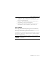
FLEX Ex Terminal Base Units Wire the Terminal Base Units Wiring Connections for Terminal Base 1797-TB3 0 1 2 3 4 5 6 7 8 10 11 12 13 14 9 15 A 16 17 21 22 23 24 25 26 18 19 20 27 28 29 30 31 32 33 B 37 38 39 40 41 42 43 44 45 34 35 36 46 47 48 49 50 51 C +V -V +V -V No connections allowed to terminals 36 and 49. WARNING 41252 Make certain that you power this terminal base unit with an intrinsically safe power supply.
FLEX Ex Terminal Base Units 9 1. Make wiring connections as described in the installation instructions included with the specific module that mounts on your terminal base. 2. Connect +V and -V from the terminal base to the next using jumpers or individual external wiring, if appropriate due to total module power consumption. Daisy-chaining You can use the daisy chain configuration if the total module power draw is <8.5 W. +V, -V Otherwise, power is connected to individual modules.
FLEX Ex Terminal Base Units Mount on a DIN Rail ATTENTION Do not remove or replace a terminal base when power is applied. Interruption of the flexbus connection can result in unintended operation or machine motion. This product is grounded through the DIN rail to the dedicated intrinsic safety ground. Use zinc-plated yellow-chromated steel DIN rail to assure proper grounding.
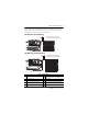
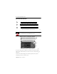
FLEX Ex Terminal Base Units 11 4. Position the terminal base over the 35 x 7.5 mm DIN rail A (A-B pt. no. 199-DR1). A A Position terminal base at a slight angle and hook over the top of the DIN rail (A). 41106 41107 Slide the terminal base tight against the adapter (or preceding terminal base). Make sure the hook on the terminal base slides under the edge of the adapter (or proceeding terminal base) and the flexbus connector is fully retracted.
FLEX Ex Terminal Base Units 5. Rotate the terminal base onto the DIN rail with the top of the rail hooked under the lip on the rear of the terminal base. Use caution to make sure that the female flexbus connector does not strike any of the pins in the mating male connector. 41108 Press down on the terminal base to lock it on the DIN rail.
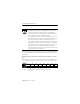
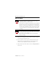
FLEX Ex Terminal Base Units 13 Mounting Dimensions 94 (3.7) 94 (3.7) mm (in.) 69 (2.7) ATTENTION 41341 The DIN rail or mounting bracket must be appropriately connected to the dedicated intrinsic safety ground. Publication 1797-5.
Publication 1797-5.1 - June 2010 mm (In. .21 (0.83) 50 (2.0) 35.5 (1.4) 71.5 (2.8) 35.5 (1.4) 35.5 (1.4) Cable length approximately 292.1 (11.5) or 901.0 (35.5) from upper connector [length depends upon cable -0.3 m (1 ft ) or 0.91 m (3 ft ). 58.5 (2.3) 40.5 (1.6) 1 +V 2 -V 3 +V .15.6 (0.61) 4 -V .
FLEX Ex Terminal Base Units 15 About the Mounting Kit Use the optional 1794-NM1 mounting kit to mount your system on a panel or wall without a DIN rail. 1794-NM1 Mounting Kit with 18 screws (2 screws for the adapter and 2 screws for each module). 30238 Repair The terminal bases are not field-repairable. Any attempt to open the terminal bases will void the warranty and the IS certification. If repair is necessary, return the module to the manufacturer. Publication 1797-5.
FLEX Ex Terminal Base Units Specifications - 1797-TB3 and 1797-TB3S Terminal Base Units Number of Terminals 1 row of 16, 2 rows of 18 1797-TB3 Terminal Screw Torque 0.8…1.0 Nm (7…9 lb-in) 1797-TB3S Terminal Type Spring-clamp - To open, insert bladed screwdriver (2.54-3.05 mm/0.100-0.120 in.) and lift up. Terminals Assignments1 +34, -35, +50, -51, and 96 PiniFemale I/O Connector Pinsi30…32, 62…64, 94…96, 36, 49 All Other Terminals Only for intrinsically safe circuits Ui <10V dc Ii <2.
FLEX Ex Terminal Base Units 17 1797-TB3 and -TB3S Specifications Continued Agency Certification IECEx Ex ia IIC T4 CENELEC II 2G Ex ia IIC T4 UL, C-UL Class I, Groups A, B, C and D; Class II, Groups E, F and G; Class III Hazardous Locations. Class I, Zone 1, AEx ib[ia] IIC T4. FM Intrinsically safe Class I, Div 1, Groups A, B, C, D, T4. Associated Apparatus with intrinsically safe Connection Class I, II, III, Div 1, Groups A--G Intrinsically safe Class I, Zone 1, AEx ib[ia] IIC T4.
FLEX Ex Terminal Base Units UL, C-UL Certification IMPORTANT For detailed certification information, refer to the FLEX Ex System Certification Reference Manual, publication 1797-6.5.6.
FLEX Ex Terminal Base Units 19 FM Certification If these products have the FM mark, they have been designed, evaluated, tested, and certified to meet the following standards: FM C1. No.3600:1998, Electrical Equipment for Use in Hazardous (Classified) Locations General Requirements FM C1. No.3610:1999, Intrinsically Safe Apparatus and Associated Apparatus for Use in Class I, II, III Division 1 Hazardous (Classified) Locations FM C1. No.
Rockwell Automation Support Rockwell Automation provides technical information on the Web to assist you in using its products. At http://support.rockwellautomation.com, you can find technical manuals, a knowledge base of FAQs, technical and application notes, sample code and links to software service packs, and a MySupport feature that you can customize to make the best use of these tools.