ControlNet Ex Media 1797-series Planning and Installation Manual
Important User Information Solid state equipment has operational characteristics differing from those of electromechanical equipment. Safety Guidelines for the Application, Installation and Maintenance of Solid State Controls (Publication SGI-1.1 available from your local Rockwell Automation sales office or online at http://www.ab.com/manuals/gi) describes some important differences between solid state equipment and hard-wired electromechanical devices.
Table of Contents Preface What’s in This Chapter . . . . Abbreviations and Symbols . Common Techniques . . . . . For More Information . . . . . . . . . . . . . . . . . . . . . . . . . . . . . . . . . . . . . . . . . . . . . . . . . . . . . . . . . . . . . . . . . . . . . . . . . . . . . . . . . . . . . . . . . . . . . . . . . 1-1 1-2 1-2 1-2 What This Chapter Contains . . . . . . . . . . . . . . . . . . . . . . . Understand the ControlNet Ex Media System . . . . . . . . . . .
Table of Contents ii Order Components . . . General Planning . . Plan a Segment . . . Plan Your Network Order Parts . . . . . . What Is Next? . . . . . . . . . . . . . . . . . . . . . . . . . . . . . . . . . . . . . . . . . . . . . . . . . . . . . . . . . . . . . . . . . . . . . . . . . . . . . . . . . . . . . . . . . . . . . . . . . . . . . . . . . . . . . . . . . . . . . . . . . . . . . . . . . . . . . . . . . . . . . . . . . . . . . . . . . . . . . . . . . . . . . . . . .
Table of Contents iii Appendix B Adjust the Cable Strip Tool What This Appendix Contains . . . . . . . . Calibrate the Cutting Blades. . . . . . . . . . Reverse and Replace the Cutting Blades. Change the Memory Blade Holder . . . . . . . . . . . . . . . . . . . . . . . . . . . . . . . . . . . . . . . . . . . . . . . . . . . . . . . . . . . . .
Table of Contents iv Publication CNET-IN003A-EN-P - January 2006
Preface What’s in This Chapter Use this manual to plan and install a ControlNet Ex media system. This manual describes the required components of an intrinsically-safe cable system and how to plan for and install these required components. This manual targets the configurion of a ControlNet Ex system. However, since a ControlNet Ex system and a ControlNet system can be linked, it may be necessary to introduce and refer to concepts on the ControlNet side of the network.
Preface 2 Abbreviations and Symbols The following table explains abbreviations and symbols we use in this manual.
Chapter 1 Overview of the ControlNet Ex Media System What This Chapter Contains Use this chapter to familiarize yourself with the ControlNet Ex media system. The following table describes what this chapter contains and where to find specific information.
1-2 Overview of the ControlNet Ex Media System Understand the ControlNet Ex Media System The ControlNet Ex media system gives you the flexibility to design a communication network for your particular application. To take full advantage of this flexibility, spend sufficient time when you plan how to install your network before you assemble any of the hardware.
Overview of the ControlNet Ex Media System Term 1-3 Means • Any physical device connecting to the ControlNet Ex or ControlNet media system that requires a network address to function on the network Node N • A network may contain a maximum of 99 nodes • This address must be in the range of 1...99 and be unique to that network.
1-4 Overview of the ControlNet Ex Media System Understand ControlNet Ex Components The ControlNet Ex media system is comprised of these components: • • • • • • • • • • • 1 Nodes Taps1 Trunk cable1 Cable connectors1 Terminators1 Segments Fiber repeater hubs (option)1 Tap terminator Network Insulators Coax barrier (option)1 For information about purchasing these components see the Allen-Bradley ControlNet Media Component List, publication AG-PA002.
Overview of the ControlNet Ex Media System 1-5 There are four styles of taps available with: • T or Y placement of BNC connectors T-tap Y-tap 40955 • Straight or right-angle connector on the drop media Straight ATTENTION Right-angle 40956 Use only intrinsically-safe taps in a ControlNet Ex media system. Intrinsically-safe taps are marked “ControlNet Ex Tap.” See page 2-2 for detailed information on taps.
1-6 Overview of the ControlNet Ex Media System Cable Connectors Use a cable connector (cat. no. 1786-BNC) to attach coax trunk cable sections to the tap’s BNC connector. T T T T N N Trunk Cable N N 40957 Optional Connectors Rockwell Automation also offers optional cable connectors for use in your network configuration. See page 2-8 for available connectors. Trunk Terminator A 75 Ω terminator (cat. no. 1797-XT) must be installed on the tap at each end of a segment.
Overview of the ControlNet Ex Media System 1-7 Tap Terminator A tap terminator (cat. no. 1797-TCAP) is available to terminate unused taps. Segment T 1797-TCAP T T T N N Trunk Cable N 40959 Use only intrinsically-safe tap terminators in a ControlNet Ex media system. Intrinsically-safe tap terminators are marked “CNet Tap Trm.” ATTENTION Segments A segment is a collection of coax trunk cable sections, taps, and two terminators.
1-8 Overview of the ControlNet Ex Media System hubs and cable length total are limited depending on your network topology. You can have a maximum of 5 repeaters in series. Safe Area Hazardous Area Coax Segment Coax Segment T T N N T T Trunk Cable N Coax (1786) Fiber Hubs Fiber Segment T H H T T T N N N Ex (1797) Fiber Hubs 41327 When you insert a fiber repeater hub into your cable system, you create a new segment.
Overview of the ControlNet Ex Media System 1-9 Two insulator kits are available: • Catalog number 1797-BOOT provides standard BNC trunk cable insulators. • Catalog number 1797-INS provides a variety of the preformed boots and insulators used with the ControlNet Ex system products. ControlNet Ex System Installation Requirements You can connect a maximum of 48 ControlNet Ex taps with a total of 250m of coax cable when using fiber hub architecture.
1-10 Overview of the ControlNet Ex Media System Catalog Number 1786-RG6 Catalog Name Description Quad-Shield, RG-6 75Ω Coax Trunk Cable 1786-BNCP, -BNCJ, BNCJI Maximum (functional) length between two 1797-TPx is 3280ft (1000m) - each 1797-TPx reduces the (functional) coax cable length by 16.3 m (53.
Overview of the ControlNet Ex Media System 1-11 UL, cUL I/O Entity Parameters and Requirements TIP Terminals Male Bus Connector For more information on UL and cUL installation requirements, refer to publication 1797-RM001, FLEX Ex System Certification Reference Manual. Vt (V) 5.8 It (mA) 400 Groups A-G Ca (µF) 3.0 La (µH) 3.
1-12 Overview of the ControlNet Ex Media System If fiber optic cable is provided with a metal shield, it must be connected to a dedicated intrinsic safety ground in the intrinsically-safe location and isolated in the non-intrinsically-safe location or be connected to a ground in the hazardous location and isolated in the intrinsically-safe location. The glass fiber must have a minimum diameter of 6µm. European Community Directive Compliance The ControlNet Ex System has the CE mark.
Overview of the ControlNet Ex Media System 1-13 Ex Directive The ControlNet Ex System is tested to meet the Council Directive 94/9 EC (ATEX 100a) Equipment and Protective Systems Intended for Use in Potentially Explosive Atmospheres by applying the following standards: • EN50014:1992, Electrical Apparatus for Potentially Explosive Atmospheres • EN50020:1994, Electrical Apparatus for Potentially Explosive Atmospheres - Intrinsic Safety “i” • EN50039:1980, Electrical Apparatus for Potentially Explosive Atmo
1-14 Overview of the ControlNet Ex Media System Notes: Publication CNET-IN003A-EN-P - January 2006
Chapter 2 Plan a ControlNet Ex Media System What This Chapter Contains Read this chapter to determine your network requirements.
2-2 Plan a ControlNet Ex Media System Determine How Many Taps You Need The number of taps you need depends on the number of devices you want to connect to the network. You need a tap for each node, repeater, or fiber hub on the network. If you plan to add nodes later, you should consider ordering and installing the cable and connectors for these additional nodes when you install the initial network. This will minimize disruption to the network during operation.
Plan a ControlNet Ex Media System 2-3 These tap kits are available (dust caps not shown): Straight T-Tap 1797-TPS Connect Programming Devices in Safe Areas Straight Y-Tap 1797-TPYS Right-Angle T-tap 1797-TPR Right-Angle Y-Tap 1797-TPYR 41330 Connect programming devices in safe areas to the ControlNet cable system through a 1784-KTCX15 communication card. Use a ControlNet tap to connect the communication card to the network. Figure 2.
2-4 Plan a ControlNet Ex Media System Fiber Media Type Fiber media type specifications are listed below. • Fiber type 62.5/125µ • Connector type ST (plastic or ceramic) • Operating wavelength 1300 nm • Optical power budge 13.3 dB You should install all fiber for your ControlNet Ex cable system in accordance with the regulations contained in applicable country codes, state codes, and applicable municipal codes (for example, National Electric Code). All metal connectors must be insulated from the ground.
Plan a ControlNet Ex Media System 2-5 requirement. The maximum allowable total length of a segment is 1,000 m (3,280 ft) with two taps connected. Each additional tap decreases the maximum length of the segment by 16.3 m (53.4 ft). The maximum number of taps allowed on a segment is 48 with a maximum length of 250 m (820 ft). IMPORTANT The derating curve is applicable only when the cable meets ControlNet attenuation specifications.
2-6 Plan a ControlNet Ex Media System EXAMPLE If your segment requires 3 taps using 1786-RG6 cable, the maximum segment length is: ([20.29 db - 3*.32 db] / 5.99 db] * 304) (19.33 db / 5.99 db) * 304 = 982 m (3227 ft) IMPORTANT The total trunk cable length or number of taps can be increased by installing a repeater hub on the segment. This creates another segment. For redundant media, decrease the number of taps by half, as shown in the derating curve.
Plan a ControlNet Ex Media System 2-7 Segment Length m (ft) 500 m (1640 ft) 250 m (820 ft) 20 2 Number of Taps With One FLEX Ex Redundant ControlNet Barrier Module Estimate Fiber Media Lengths The maximum length of a fiber media section for the 1797-RPFM module is dependent on the quality of the fiber, number of splices, and the number of connectors. The total attenuation for a cable section must be less than 13.3 dB. Typically, cable attenuation for a wavelength of 1300 nm is less than 1.5 dB/km.
2-8 Plan a ControlNet Ex Media System After you have determined the number of segments in your network, multiply this number by two to determine how many terminators you need for your network. IMPORTANT Determine What Type of Connectors You Need To comply with intrinsic safety standards, be sure to cover the exposed metal with the intrinsically-safe insulator provided with each terminator. Use the following table to determine what type of connectors you need.
Plan a ControlNet Ex Media System In This Example, ControlNet Ex Cable: Cable Enters and Exits From the Side Panel Wall • Enters and exits the panel enclosure from the side using isolated-bulkhead connectors 2-9 Isolated-bulkhead Connectors Bullet Connector Barrel Connector • Contains two adjacent taps connected by a barrel connector • Reserves one future tap location with a bullet Right Angle Connectors ATTENTION TIP Taps 20091m Do not let any metallic surfaces on the BNC connectors, plugs, or
2-10 Plan a ControlNet Ex Media System Use Redundant Media in a Hazardous Area You can run a second trunk cable between your ControlNet Ex nodes for redundant media. With redundant media, nodes send signals on two separate segments. The receiving node compares the quality of the two signals and accepts the better signal to permit use of the best signal. This also provides a backup cable should one cable fail.
Plan a ControlNet Ex Media System 2-11 • Install the cable system so that the trunk cables at any physical device location can be easily identified and labeled with the appropriate icon or letter. Each redundant ControlNet Ex device is labeled so you can connect it to the corresponding trunk cable. • Both trunk cables (trunk cable A and trunk cable B) of a redundant-cable network must have identical configurations. Each segment must contain the same number of taps, nodes and fiber repeaters.
2-12 Plan a ControlNet Ex Media System • Avoid connecting a single node’s redundant trunk cable connections on different segments; this will cause erratic operation. Safe Area Hazardous Area 1786 Fiber Repeater Hubs Segment 1 1797 Fiber Repeater Hubs . . . A-B Q UALITY A-B Allen-Bradley Q UALI TY 1797 - RPA Allen-Bradley A-B 1797 - RPFM Q UALITY Module Status .
Plan a ControlNet Ex Media System Application Considerations 2-13 The following guidelines coincide with the guidelines for the installation of electrical equipment to minimize electrical noise inputs to controllers from external sources contained in IEEE standard 518-1982. When planning your cable system keep these installation considerations in mind. ATTENTION These guidelines apply only to noise coupling. Intrinsic safety requirements for cable mounting are of the highest priority.
2-14 Plan a ControlNet Ex Media System General Wiring Guidelines Follow these guidelines with regard to noise coupling. Following intrinsic safety requirements should prevent most or all of these situations from occurring. These guidelines are provided as a general reference for wiring. • If wiring must cross power feed lines, it should do so at right angles. • Route wiring at least 1.5 m (5 ft) from high-voltage enclosures, or sources of rf/microwave radiation.
Plan a ControlNet Ex Media System 2-15 When you run cable inside an enclosure, route conductors external to all raceways in the same enclosure, or in a raceway separate from Category-1 conductors. Route Your Cable At Least 0.08 m (3 in.) 0.15 m (6 in.) 0.6 m (24 in.
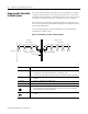
2-16 Plan a ControlNet Ex Media System Add Ferrite Beads Wrap the IS power input cable two turns around the ferrite bead before connecting the terminal block to the adapter. Five ferrite beads come with the adapter. Four are short and identical. Use these on the ControlNet Ex trunk cable. The fifth, longer ferrite bead is for the adapter power cable. 42206 Add ferrite beads on the ControlNet Ex trunk cable inside the cabinet wherever the trunk cable goes into or out of the cabinet.
Plan a ControlNet Ex Media System Order Components 2-17 Now that you are ready to begin ordering components, use these guidelines to help you select components. General Planning The ControlNet Ex cable system is isolated from earth and must be protected from inadvertent ground connections. Plan a Segment Refer to this list when you plan a segment.
2-18 Plan a ControlNet Ex Media System Plan Your Network Refer to this list when you plan your network.
Plan a ControlNet Ex Media System Item Cat. No. Guidelines Coax Tool Kit 1786-CTK Use the tool kit to create your trunk cable One to your specifications. 2-19 Required Quantity1 1 You will need to double your quantities when ordering components for a redundant cable system. 2 The connector kit may be shipped with two ferrules. The smaller diameter ferrule should not be used with ControlNet Ex applications.
2-20 Plan a ControlNet Ex Media System What Is Next? Publication CNET-IN003A-EN-P - January 2006 After you gather all of the parts for your ControlNet Ex media system, you are ready to go to Chapter 3 to begin the installation of your network.
Chapter 3 Install a ControlNet Ex Media System What This Chapter Contains Follow the instructions in this chapter to install your ControlNet Ex media system.
3-2 Install a ControlNet Ex Media System Wire Inside Enclosures When the RG-6 type coax cable is not being pulled through conduit, follow these specifications. For This Coax Cable PVC Tap drop-cable The Bend Radius Should Not Exceed 38.1 mm (1.5 in.) 25.4 mm (1.0 in.) The 1797-EXMK Cable Marking kit is available for clearly marking drop cables and trunk cables as intrinsically-safe. Mount the Taps First select where you want to mount the taps, then use this mounting procedure.
Install a ControlNet Ex Media System ATTENTION 3-3 Do not allow any metal portions of the tap, such as the universal mounting bracket screws or connectors, to contact any conductive material. This contact could cause noise on the network. Also be certain all exposed metal is covered by either the intrinsically-safe insulators or tape having a 500V dielectric rating.
3-4 Install a ControlNet Ex Media System Mount a Tap with a Universal Mounting Bracket 1. Align the universal mounting bracket with the mounting holes on the tap. 2. Use the screws provided with the tap to attach the tap to the universal mounting bracket. Universal Mounting Bracket Y-Tap Dust Cap T-Tap Universal Mounting Bracket (Provided With Tap) Dust Cap 20084-M 20080-M Use only the screws that are packaged with the tap. They are the proper length and head style.
Install a ControlNet Ex Media System 3-5 3. Mount the tap and bracket assembly to a DIN rail or another mounting surface. DIN Mounting Rail Another Mounting Surface Universal Mounting Bracket Universal Mounting Bracket Use four screws to attach the universal mounting bracket to another mounting surface. DIN Rail Suitable Fixture 20081-M 20082-M Mount the universal mounting bracket on specified Allen-Bradley mounting rails or #3 style symmetrical DIN rails (35 mm X 7.5 mm [1.38 in. x 0.30 in.
3-6 Install a ControlNet Ex Media System Mount a Tap Through the Body Holes TIP A suitable fixture (mounting surface) can be conductive or grounded because the mounting holes are electrically isolated. Mount the tap to a suitable fixture by using a tie wrap, or screws and flat washers. Tie Wrap Screws and Flat Washers Screws and Flat Washers (Not Supplied) Body Holes Body Holes Tie Wrap 41645 You can use a variety of screw types. ATTENTION Specifications 41646 Do not over-tighten the screws.
Install a ControlNet Ex Media System 3-7 Installation in Zone 1 The 1797-RPA and 1797-RPFM modules must not be exposed to the environment. You must install these modules in a metal enclosure. This repeater hub has a protection factor of IP20. ATTENTION These modules cannot be used in a hazardous environment after they have been exposed to non-intrinsically-safe signals. Electrostatic Charge Attention: Avoid electrostatic charge. Protect the system against electrostatic charge.
3-8 Install a ControlNet Ex Media System Ex Directive This product is tested to meet the Council Directive 94/9 EC (ATEX 100a) Equipment and Protective Systems Intended for Use in Potentially Explosive Atmospheres by applying the following standards: • EN50014:1992, Electrical Apparatus for Potentially Explosive Atmospheres • EN50020:1994, Electrical Apparatus for Potentially Explosive Atmospheres - Intrinsic Safety “i” • EN50039:1980, Electrical Apparatus for Potentially Explosive Atmospheres - Intrinsic
Install a ControlNet Ex Media System 3-9 Mount the Fiber Repeater Hub Follow this procedure to mount the fiber repeater hub. 1. Position the module on a 35 mm x 7.5 mm (1.38 in. x 0.30 in.) DIN rail (A-B part number 199-DR1) at approximately a 30° angle. 41167 2. Hook the lip on the rear of the adapter onto the top of the DIN rail, and rotate the module onto the rail. 41166 3. Press the adapter down onto the DIN rail until flush.
3-10 Install a ControlNet Ex Media System 4. If the adapter does not snap into position, use a screwdriver or similar device to move the locking tab down while pressing the module flush onto the DIN rail. Release the locking tab to lock the module in place. If necessary, push up on the locking tab to lock. 41168 5. Remove the adapter backplane connector cover. 6. Follow steps 1 through 4 to attach fiber modules to the DIN rail. 7.
Install a ControlNet Ex Media System 3-11 Connect the Fiber Repeater Hub to a ControlNet Ex Network 1. Connect to the ControlNet Ex coax network with the drop line of the Ex coax tap to the adapter BNC connector. Intrinsically-safe Insulator 41170 2. Connect the fiber media to the fiber module by attaching the receive and transmit fibers to either the left or right set of receive and transmit ports. Make note of which fiber is receive and which is transmit.
3-12 Install a ControlNet Ex Media System 4. Apply +V and -V power from a 1797 power supply to the adapter through a removable terminal block. +V -V +V -V +V -V +V -V 41297 Screw terminals and spring terminals are provided. 5. Strip the +V and -V wires to a length so that no bare conductor shows after inserting the wires into position. 6. If you are using the spring terminals of the plug, insert a screwdriver into the slot and carefully pry until the spring clamp opens to accept the wire. .
Install a ControlNet Ex Media System Install Cable Connectors 3-13 After you have mounted the taps, you need to attach cable connectors to the ends of your trunk cable sections. Collect Your Tools To install the cable connectors, we recommend that you use the tools in the ControlNet Coax Toolkit, catalog number 1786-CTK.
3-14 Install a ControlNet Ex Media System Strip the Cable When you cut cable sections, make them long enough to route from one tap to the next with sufficient length so that the bend radius is not less than: • 76.2 mm (3 in.) for wiring external to enclosures • 38.1 mm (1.5 in.) for wiring inside enclosures ATTENTION Be certain to perform the calibration procedure the first time you use the tool and every time you change the blade or both memory cartridges.
Install a ControlNet Ex Media System 3-15 4. Lock the cable into place by moving the chamber-gauge ring forward until it meets the cable with slight resistance. 20073 This gauge moves two rollers toward the cable and regulates the depth of the cut. The gauge will click as it moves from one gauge to the next. 5. Hold the cable in one hand, place the index finger of your other hand inside the chamber-gauge ring and turn the strip tool 360° around the cable.
3-16 Install a ControlNet Ex Media System 6. After you have moved the chamber gauge ring to the last position and turned the strip tool the final time: a. Move the chamber-gauge ring backward to release the strip tool and remove it from the cable. b. Slip the crimp ferrule onto the cable. Push it back to the sheath area of the cable to keep it out of the way for the moment. Crimp Ferrule 41887a Cable c. Strip away the appropriate portion of the cable without using the strip tool. d.
Install a ControlNet Ex Media System 3-17 Be sure to strip the cable to expose these layers of the cable: All Four Shield Layers Braid/Tape/Braid/Tape White Foam Electric Or 1st Tape, If Tape Is Bonded Center Conductor 8.3 mm (0.33 in.) 3.7 mm (0.15 in.) 4.0 mm (0.16 in.) 20076a IMPORTANT If you do not see the three distinct layers of cable or if the outer braid has been scored or cut, snip off the exposed end with the wire cutters and repeat the entire cable-stripping process.
3-18 Install a ControlNet Ex Media System Use the imprint guide on the back of the ControlNet tap or the calibration tool to verify this. T-Tap 3.7 mm (0.15 in.) 8.3 mm (0.33 in.) 4.0 mm (0.16 in.) PVC Cable Center Conductor PVC Cable Only PVC/CL2 FEP/CL2P PVC/CL2 FEP/CL2P Calibration/flare Tool The center conductor should be exactly 4.0 mm (0.16 in.). If the center conductor is too long, cut off the excess with the wire cutter from the cable kit.
Install a ControlNet Ex Media System 3-19 Test for Electrical Shorts and Continuity Between the Center Conductor and the Shield 1. The NetLinx Media Checker (catalog number 1788-MCHKR) is the preferred tool for continuity testing. Attach the connector end of the cable to the port on top of the media checker. Attach the connector end of the cable to the port on top of the media checker. MediaChecker 1788-MCHKR SETUP ENTER LENGTH TEST WIRE MAP OFF 31195-M 2.
3-20 Install a ControlNet Ex Media System IMPORTANT Replace the trunk cable section if problems persist with the cable after completing these tests. Attach the Connectors to the Cable 1. Push the calibration/flare tool onto the cable and with a slight twisting motion (with sufficient inward pressure) to expand the braid. 41888 Push the calibration/flare tool gently and rotate slightly onto the connector while you apply pressure.
Install a ControlNet Ex Media System 3-21 2. Place the center pin over the center conductor. Center centerConductor conductor 41889 Center center Pin pin IMPORTANT Sometimes strands of insulation are left on the center conductor. Be certain that the center conductor is clean before you install the center pin. Be certain that the center pin slips onto the center conductor completely. The back shoulder of the center pin should be up against the white insulation.
3-22 Install a ControlNet Ex Media System 3. With the center pin in place, use the crimp tool to crimp the pin into place. The smaller hexagonal crimping notch is for crimping the center pin onto the center connector. 41903 Check for braid strands that could cause a short to center conductor. 4. Slide the ControlNet connector onto the cable.
Install a ControlNet Ex Media System 3-23 5. Slide the crimp ferrule over the three outer shields and connector base until it meets the shoulder on the connector. 20077e 6. Use the crimp tool to crimp the ferrule. Position the crimp tool on the ferrule as close as possible to where the connector base and ferrule meet. Press the tool tightly around the ferrule until the crimp tool releases. The larger hexagonal crimping notch is for crimping the ferrule which holds the connector to the cable.
3-24 Install a ControlNet Ex Media System Test for Electrical Shorts and Continuity Between the Connector Body and Pin 1. Use an ohmmeter or continuity tester to test for a short between the connector body and pin. Attach the connector end of the cable to the port on top of the media checker. MediaChecker 1788-MCHKR SETUP ENTER LENGTH TEST WIRE MAP OFF 31195-M If Resistance Reading Indicates Then That a short exists Continue to next section.
Install a ControlNet Ex Media System 3-25 3. At the same end of the cable tested in step 1, use an ohmmeter or continuity tester to test for electrical continuity. Attach the connector end of the cable to the port on top of the media checker. MediaChecker 1788-MCHKR SETUP ENTER LENGTH TEST WIRE MAP OFF 31195-M If Resistance Reading Indicates Then That a short exists Continue to next section.
3-26 Install a ControlNet Ex Media System 1. Connect one end of the trunk cable section to one of the tap BNC connectors. 20078 2. Slide the intrinsically-safe blue insulator over the BNC connector to cover any exposed metal. 3. Install a 75Ω terminator onto the tap’s other BNC connector. Repeat steps 1 and 2 at the other end of the segment.
Install a ControlNet Ex Media System Connect Devices 3-27 After you terminate your segments, connect your devices. To Connect a Fiber repeater hub ControlNet Ex adapter See Page 3-11 Procedure below 1. Remove and save the blue dust cap (on the straight or right-angle connector). 2. Replace the dust cap with the blue intrinsically-safe insulator ring. 3. Connect the straight or right-angle connector to your device.
3-28 Install a ControlNet Ex Media System Install the 1797-BCNR Module You can also use the 1797-BCNR FLEX Ex Redundant ControlNet Barrier Module to interconnect between ControlNet coax and ControlNet Ex networks. This module provides an alternative to installing ControlNet coax and Ex fiber repeater modules. Use the 1797-BCNR FLEX Ex ControlNet barrier module in Class I, Divison 2 or Zone 2 safe areas, as shown in the figure. Figure 3.
Install a ControlNet Ex Media System 3-29 3. Ensure the locking tabs snap into place. IMPORTANT Connect the ControlNet Ex side of the barrier module to either a 1797-ACNR15 FLEX Ex I/O module or a 1797-TCAP FLEX Ex Safe Tap Dummy Load using only ControlNet Ex Taps (such as 1797-TPR, 1797-TPYR, 1797-TPS, or 1797-TPYS). 4. Remove the insulator boot from the terminals. 5. Connect the trunk cable as shown in the illustration.
3-30 Install a ControlNet Ex Media System Notes: Publication CNET-IN003A-EN-P - January 2006
Appendix A Mounting Dimensions What This Appendix Contains Use these mounting dimensions to mount your taps, universal mounting brackets, and repeaters. Tap Placement Make copies of these templates as necessary to help you mark placement for your taps. Y-Tap T-Tap 35.66 mm (1.40 in.) 30.23 mm (1.19 in.) 15.24 mm (0.60 in.) 33.02 mm (1.30 in.) 15.24 mm (0.60 in.) 25.44 mm (1.00 in.) 39.37 mm (1.55 in.) 31.37 mm (1.235 in.) 127 mm (5/16 in.) Mounting Holes 127 mm (5/16 in.
A-2 Mounting Dimensions Universal Mounting Bracket 58.42 mm (2.30 in.) 49.53 mm (1.95 in.) 15.47 mm (0.609 in.) 30.94 mm (1.128 in.) 19.05 mm (0.75 in.) 9.53 mm (0.375 in.
Appendix B Adjust the Cable Strip Tool What This Appendix Contains Follow the instructions in this appendix to calibrate the cable strip tool supplied with the ControlNet Coax Toolkit (1786-CTK). Calibrate the Cutting Blades Use the following procedure to calibrate your cable strip tool to cut FEP or PVC cable. 1. Turn the three screws outward to back the blades out. This prevents the calibration tool from bottoming out. 2.
B-2 Adjust the Cable Strip Tool 6. Retract the handle of the cable strip tool. 7. Remove the calibration tool from the cable strip tool. When you have finished, the blade should make a cut of the following dimensions in your cable. 8.3 mm (0.33 in.) 3.7 mm 4.0 mm (0.15 in.) (0.16 in.) 30030-m First Cut: All Four Shield Layers-braid/tape/braid/tape The first cut should cut the outer sheath without cutting the outer wire braid.
Adjust the Cable Strip Tool Reverse and Replace the Cutting Blades B-3 To reverse or change the cutting blades: 1. Use a screwdriver to lift the memory blade holder and swing it back. 20182-m 2. Slide the memory blade cartridge out of the strip tool. 20183-m If You Are Go To Reversing the memory blade cartridge The next step to use the second set of blades Replacing the memory blade cartridge Step 4 3. Flip the memory blade cartridge and slide it back into the strip tool.
B-4 Adjust the Cable Strip Tool 30031-m Go to step 5. 4. Align the memory blade cartridge (the side with the raised notches) to the raised area on the inside of the strip tool and slide the new memory blade cartridge in. Raised Notch Raised Area 30031a-m TIP The blades should be on top as you slide the cartridge in. 5. Swing the memory blade holder closed.
Adjust the Cable Strip Tool Change the Memory Blade Holder B-5 You received two memory blade holders with your cable strip tool; one is for PVC-CL2 cable, and the other is for plenum FEP-CL2P cable. You need to install the appropriate memory blade holder for the type of cable you are stripping (PVC or FEP). 1. Lift the latches on the memory blade holder and swing it back. 20182-m 2. Snap the memory blade holder off the rod and remove it from the strip tool. 20070-m 3.
B-6 Adjust the Cable Strip Tool Notes: Publication CNET-IN003A-EN-P - January 2006
Appendix C Protect Your System Against Electrostatic Discharge Protect the system against electrostatic charge. Post a sign near this module: Attention: Avoid electrostatic charge. For your convenience, we provide some signs you can cut out below. Post these labels or something similar beside each module to protect the system against electrostatic charge. Attention: Avoid electrostatic charge. Attention: Avoid electrostatic charge. Attention: Avoid electrostatic charge.
C-2 Protect Your System Against Electrostatic Discharge Notes: Publication CNET-IN003A-EN-P - January 2006
Index redundant media 2-10 repeater 1-2, 1-7, 2-8 segment 1-7, 2-17 stripping trunk cable 3-14 surge suppression 2-15 tap 1-2, 1-4, 2-2, 2-18 mounting dimensions A-1 terminating segments 3-25 terminator 2-18 terminators 1-3, 2-7 testing for electrical continuity 3-19, A abbreviations and symbols 1-2 about this manual 1-1 application considerations 2-13 B barrel connector 2-8 BNC cable connectors 1-6, 2-8 installing 3-13 bridge 1-2 bullet connector 2-2, 2-8 C cable connectors 1-6, 2-8 barrel 2-8 bullet 2-
2 Index N NetLinx Media Checker 3-19 node 1-4 O ohmmeter 3-19 ordering components 2-17 P programming terminals ways to connect to a ControlNet link 2-3 publications 1770-4.
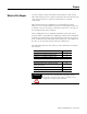
How Are We Doing? Your comments on our technical publications will help us serve you better in the future. Thank you for taking the time to provide us feedback. You can complete this form and mail (or fax) it back to us or email us at RADocumentComments@ra.rockwell.com Pub. Title/Type ControlNet Ex Media Planning and Installation Manual Cat. No. 1797-series Pub. No. CNET-IN003A-EN-P Pub. Date January 2006 Part No. 957208-04 Please complete the sections below.
PLEASE FASTEN HERE (DO NOT STAPLE) PLEASE FOLD HERE NO POSTAGE NECESSARY IF MAILED IN THE UNITED STATES BUSINESS REPLY MAIL FIRST-CLASS MAIL PERMIT NO.
Rockwell Automation Support Rockwell Automation provides technical information on the web to assist you in using our products. At http://support.rockwellautomation.com, you can find technical manuals, a knowledge base of FAQs, technical and application notes, sample code and links to software service packs, and a MySupport feature that you can customize to make the best use of these tools.