
User Manual

FLEX Ex I/O 24V DC 4 Non-Isolated Source Output Module 9
Publication
1797-5.6 - June 2011
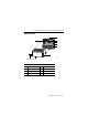
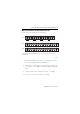
Wire to a 1797-TB3 or 1797-TB3S Terminal Base Unit
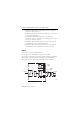
Connect wiring to the terminal base as shown below.
1. Co
nnect the individual output wiring to (+) terminals (0, 4, 8, 12) on
the 0…15 row (A) as indicated in the table below.
2. Co
nnect the associated output to the corresponding (-) terminal (1, 5,
9, 13) on the 0…15 row (A) for each output as indicated in the table
below.
3. Con
nect +V DC power to terminal 34 on the 34…51 row (C).
4. Con
nect -V to terminal 35 on the 34…51 row (C).
No connections allowed to terminals 2, 3, 6, 7, 10, 11, 14, 15, 17 to 32, 36, 37, 38, 39,
46, 47, 48, 49.
0 1 2 3 4 5 6 7 8 9 10 11 12 13 14 15
16 17 18 19 20 21 22 23 24 25 26 27 28 29 30 31
34 35 36 37 38 39 40 41 42 43 44 45 46 47 48 49
32 33
50 51
CH 0 CH 1 CH 2 CH 3
+
_
+
_
+
_
+
_
+V -V+V -V
40068A
Row A
Row B
Row C