
User Manual
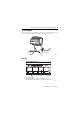

FLEX Ex I/O 24V DC 4 Non-Isolated Source Output Module 13
Publication
1797-5.6 - June 2011
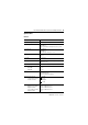
Overload Alarm 0 = No fault
1 = Output channel overloaded
(Load resistance range 30…5000 Ω)
100 Hz (10 ms) filter is integrated
Data Output data
0 = Off
1 = On
Default = 0
Fault State 0 = Output goes to 0 during fault
1 = Hold last state
Default = 0
Detect Alarms These bits can be used to activate/deactivate
wire-off detection and
overload monitoring of the outputs for each channel.
0 = Wire-off detection/overload monitorin
g deactivated
1 = Wire-off detection/overload monitorin
g activated
Note: Leakag
e current will be present when output is at 0 state if Wire Off
detection is activated. The normal load range is defined as 30
Ω…5
k
Ω
.
In
this range, no faults will occur. Wire off is assured to be reported for loads
> 75
k
Ω
.
It does not matter if the output is OFF or ON.
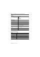
Latch Alarms
This bit defines for all channels, whether, in the event of a wire off or overload
fault, the corresponding fault bit (Overload Alarm, Fault Alarm) remains set
until the Reset Alarms bit in the configuration data word is reset by the user.
This ensures that a fault message is sent to the control system in the event of
a fault that is short in duration. The alarms should be latched if the Latch
Alarms bit is 1 and the outputs go to 0 state until the Reset Alarm occurs.
0 = Alarms and outputs are automatically reset
1 = Alarms and outputs are blocked and must be reset by setting the bit
Re
set Alarms through the user program.
Default = 0
Outputs Enable 0 = Outputs disabled
1 = Outputs enabled
Default = 0
This bit must be set to 1 by the program for normal operation of the
outpu
ts. When set to 0 the outputs will follow the Fault State status.
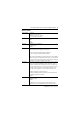
Field Descriptions