
User Manual
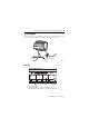

12 FLEX Ex I/O 24V DC 4 Non-Isolated Source Output Module
Publication
1797-5.6 - June 2011
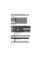
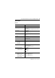
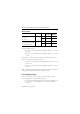
Memory Mapping
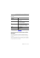
Status Indicators
Indicator Status Description
Yellow Individual input present
Flashing red Channel fault
Solid red Module did not pass power up check
Channel 0 is solid red while power-up check is running
Dec
Bit
15 14 13 12 11 10 09 08 07 06 05 04 03 02 01 00
Oct
Bit
17 16 15 14 13 12 11 10 07 06 05 04 03 02 01 00
Read 0 OVL
3
OVL
2
OVL
1
OVL
0
F3 F2 F1 F0
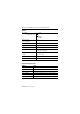
Write 0 Out
Enb
LDA
3
DA
2
DA
1
DA
0
FS
3
FS
2
FS
1
FS
0
D3 D2 D1 D0
Configuration 1 RA Alarm Filter
Ch 0…3
Where: OVL = Overload alarm for individual channel
F = Fault alarm for individual channel
DA = Detect Alarms, Detection of Output faults (0 = Disable, 1 = Enable)
FS = Fault state (0 is reset and 1 is hold last state)
D = Data, Output data 0 = Off 1 = On
L = Latch alarms (0 = Disable, 1 = Enable)
Out Enb = Output Enable
RA = Reset Alarms (0 = Normal, 1 = Reset)
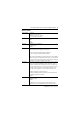
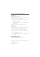
Field Descriptions
Field Description
Fault Alarm 0 = No fault
1 = Wire-off fault or overload
100 Hz (10 ms) filter is integrated
Note:
A wire-off fault or overload can be detected using this single bit.