Installation Instructions FLEX Ex I/O 24V DC 4 Non-Isolated Source Output Module Catalog Number 1797-OB4D Topic Page Important User Information 2 Installation in Zone 1 5 Installation on Zone 22 5 Module Installation 3 Outputs 8 Wire to a 1797-TB3 or 1797-TB3S Terminal Base Unit 9 Ground the Module 11 Indicators 11 Memory Mapping 12 Field Descriptions 12 Repair 14 Specifications 15 Cooperative Operation of the ControlNet Ex Adapter and FLEX Ex Output Modules 17 FLEX Ex Output M
FLEX Ex I/O 24V DC 4 Non-Isolated Source Output Module Important User Information Solid state equipment has operational characteristics differing from those of electromechanical equipment. Safety Guidelines for the Application, Installation and Maintenance of Solid State Controls (Publication SGI-1.1 available from your local Rockwell Automation sales office or online at http://www.literature.rockwellautomation.
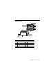
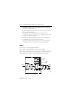
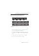
FLEX Ex I/O 24V DC 4 Non-Isolated Source Output Module 3 Module Installation 2 1 3 4 5 6 8 7 40231 Label here or under here Component identification 1 FlexBus connector 5 Terminal base unit 2 Latching mechanism 6 Alignment groove 3 Keyswitch 7 Alignment bar 4 Cap plug 8 Module Publication 1797-5.
FLEX Ex I/O 24V DC 4 Non-Isolated Source Output Module Install the Module ATTENTION This equipment is considered Group 1, Class A industrial equipment according to IEC/CISPR Publication 11. Without appropriate precautions, there may be potential difficulties ensuring electromagnetic compatibility in other environments due to conducted as well as radiated disturbance. This equipment is supplied as open-type equipment.
FLEX Ex I/O 24V DC 4 Non-Isolated Source Output Module 5 6. Make certain that you only connect terminal base units to other intrinsically safe system modules or adapters to maintain the integrity of the intrinsically-safe backplane. 41307 7. Remove the cap plug (4) and attach another intrinsically safe terminal base unit to the right of this terminal base unit if required. Installation in Zone 1 This module must not be exposed to the environment and must have a suitable metal enclosure.
FLEX Ex I/O 24V DC 4 Non-Isolated Source Output Module The IS-RPI cabinets (type IVK2-ISRPI-V8LC, IVK2-ISRPI-V8HYW, or IVK2-ISPRI-V16LC) ensures the basic protection for the intrinsically safe apparatus of the FLEX Ex system for use in Zone 22.
FLEX Ex I/O 24V DC 4 Non-Isolated Source Output Module 7 Removal and Insertion Under Power WARNING These modules are designed so you can remove and insert them under power. However, take special care when removing or inserting modules in an active process. I/O attached to any module being removed or inserted can change states due to its input/output signal changing conditions. If you insert or remove the terminal base while backplane power is on, an electrical arc can occur.
FLEX Ex I/O 24V DC 4 Non-Isolated Source Output Module • EN60079-11:2007, Explosive atmospheres - Part 11 : equipment protection by intrinsic safety "i" • EN60079-0:2006, Electrical apparatus for explosive gas atmospheres Part 0 : general requirements • EN 60079-26 : 2004, Electrical apparatus for explosive gas atmospheres - Part 26 : construction, test and marking of Group II Category 1 G electrical apparatus • EN61241-0 : 2006, Electrical apparatus for use in the presence of combustible dust - Part 0: G
FLEX Ex I/O 24V DC 4 Non-Isolated Source Output Module 9 Wire to a 1797-TB3 or 1797-TB3S Terminal Base Unit Connect wiring to the terminal base as shown below.
FLEX Ex I/O 24V DC 4 Non-Isolated Source Output Module WARNING Make certain that you power this module with an intrinsically safe power supply. Do not exceed the values listed in the specifications for this module. If you connect or disconnect wiring while the field-side power is on, an electrical arc can occur. This could cause an explosion in hazardous location installations. Be sure that power is removed or the area is nonhazardous before proceeding. 5.
FLEX Ex I/O 24V DC 4 Non-Isolated Source Output Module 11 Ground the Module All I/O wiring must use shielded wire. Shields must be terminated external to the module, such as bus bars and shield-terminating feed throughs. Shield terminating feed-through Bus bar 30820-M Indicators Ex 1797-OB4D PWR A B C A = Status indicators B = Insertable labels for writing individual input designations C = Power indicator (green indicates power applied to the module) 40067 Publication 1797-5.
FLEX Ex I/O 24V DC 4 Non-Isolated Source Output Module Status Indicators Indicator Status Description Yellow Individual input present Flashing red Channel fault Solid red Module did not pass power up check Channel 0 is solid red while power-up check is running Memory Mapping Dec Bit 15 14 13 12 11 10 09 08 07 06 05 04 03 02 01 00 Oct Bit 17 16 15 14 13 12 11 10 07 06 05 04 03 02 01 00 Read 0 OVL 3 OVL 2 OVL 1 OVL 0 F3 F2 F1 F0 Write 0 Out Enb L DA 3
FLEX Ex I/O 24V DC 4 Non-Isolated Source Output Module 13 Field Descriptions Overload Alarm 0 = No fault 1 = Output channel overloaded (Load resistance range 30…5000 Ω) 100 Hz (10 ms) filter is integrated Data Output data 0 = Off 1 = On Default = 0 Fault State 0 = Output goes to 0 during fault 1 = Hold last state Default = 0 Detect Alarms These bits can be used to activate/deactivate wire-off detection and overload monitoring of the outputs for each channel.
FLEX Ex I/O 24V DC 4 Non-Isolated Source Output Module Field Descriptions Alarm Filter These 3 bits are used to set the time constant of the fault/overload alarm filter for channels 0…3. Default = 0 Value Binary Reset Alarms Time constant 000 0.25 ms (Hardware) 001 0.5 ms 010 1 ms 011 2 ms 100 4 ms 101 8 ms 110 16 ms 111 32 ms With this bit, wire off/overload faults are reset and the latch condition of the outputs cancelled. See Latch Alarms (LA).
FLEX Ex I/O 24V DC 4 Non-Isolated Source Output Module 15 Specifications General Attribute Value Number of outputs 4, nonisolated, sourcing IS output type Ex ia IIB/IIC T4, AEx ia IIC T4, Class I, II, III Division 1 Groups A, B, C, D, E, F, G T4 IS module type Ex ib IIB/IIC T4, AEx ib IIC T4, Class I Division 1 Groups A…D T4 V-I Characteristics Refer to Output Voltage versus Current Capability on page 29 Load range 30…5000 Ω Fault detection Fault bits in data table and LED (per channel) blinki
FLEX Ex I/O 24V DC 4 Non-Isolated Source Output Module General Power supply (+V, -V Intrinsically safe) Ui < 9.5V DC Ii < 1 A Li = Negligible Ci = Negligible Module field-side power consumption 7.5 W Power dissipation 5W Thermal dissipation 17.07 BTU/hr Module location 1797-TB3 or 1797-TB3S Terminal base unit Conductors wire size, max 4 mm2 (12 gauge) stranded 1.2 mm (3/64 in.) insulation Dimensions HxWxD 46 x 94 x 75 mm (1.8 x 3.7 x 2.95 in.) Weight, approx. 200 g (7.05 oz.
FLEX Ex I/O 24V DC 4 Non-Isolated Source Output Module 17 Certifications Certifications when product Value is marked (1) CENELEC II (1) 2G Ex ib[ia] IIC T4 II (1) D [Ex iaD] UL, C-UL Class I, Groups A, B, C and D; Class II, Groups E, F and G; Class III Hazardous Locations Class I, Zone 1, AEx ib[ia] IIC T4. FM Intrinsically safe Class I, Div 1, Groups A, B, C, D, T4. Associated Apparatus with instrincally safe connections Class I, II, III, Div 1, Groups A-G.
FLEX Ex I/O 24V DC 4 Non-Isolated Source Output Module Adapter Operation Network Communication Monitoring The adapter is the primary monitor of network activity. If it detects loss of network communication, it can be programmed to: • continue writing the last valid received data to the module (hold last state). • apply local module safe states.(1) • write a programmable fault state value to the module, depending upon the module type.
FLEX Ex I/O 24V DC 4 Non-Isolated Source Output Module 19 Flexbus Communication Monitoring The module monitors FlexBus communication activity and the state of its Output Enable bit. If it detects loss of FlexBus communication activity or the Output Enable bit transitioning to 0, it can be programmed to: • continue writing the last valid received data to the outputs (hold last state). • reset the outputs. • write the local module fault state value to the output, depending upon the module type.
FLEX Ex I/O 24V DC 4 Non-Isolated Source Output Module Entity Parameters 1797-OB4D Uo = 27.4V Io = 110 mA Protection Group Allowed Allowed Capacitance Inductance Ex ia IIB 677 nF 8 mH IIC 87 nF 2 mH IIB 150 nF 5 mH IIC 30 nF 2 mH Ex ia If concentrated capacitance and/or inductance are available, use the following values.
FLEX Ex I/O 24V DC 4 Non-Isolated Source Output Module 21 • UL 1203, Explosion-Proof and Dust-Ignition-Proof Electrical Equipment for Use in Hazardous (Classified) Locations • UL 2279, Electrical Equipment for Use in Class I, Zone 0, 1, and 2 Hazardous (Classified) Locations • UL 61010, UL Standard for Safety Electrical Equipment For Measurement, Control, and Laboratory Use; Part 1: General Requirements • CSA C22.2 No.
FLEX Ex I/O 24V DC 4 Non-Isolated Source Output Module Ex 1797-OB4D FLEX Ex digital output I/O module Key position for terminal base insertion PWR Indicators Male bus connection Female bus connection Terminal base key Terminal base Field wiring terminals IMPORTANT 42058 A terminal base may or may not have an I/O module installed. Publication 1797-5.
FLEX Ex I/O 24V DC 4 Non-Isolated Source Output Module 23 Hazardous (Classified) Location Class I, Zones 0, 1, & 2 Groups IIC, IIB, IIA Class I, Div. 1 & 2 Groups A, B, C, D Class II, Div. 1 & 2 Groups E, F, G Class III, Div. 1 & 2 Any Simple Apparatus or I.S. device with Entity Concept parameters (Vmax, Imax, Ci, Li) appropriate for connection to associated apparatus with Entity Concept parameters listed in the table, Terminal Connections.
FLEX Ex I/O 24V DC 4 Non-Isolated Source Output Module The values of Lo and Co listed in the table above are allowed if one of the following conditions is met: • The total Li of the external circuit (excluding the cable) is < 1% of the Lo value or • The total Ci of the external circuit (excluding the cable) is < 1% of the Co value.
FLEX Ex I/O 24V DC 4 Non-Isolated Source Output Module 25 • FM C1. No.3600:1998, Electrical Equipment for Use in Hazardous (Classified) Locations General Requirements • FM C1. No.3610:1999, Intrinsically Safe Apparatus and Associated Apparatus for Use in Class I, II, III Division 1 Hazardous (Classified) Locations • FM C1. No.3615:1989, Explosionproof Electrical Equipment General Requirements • FM C1. No.
FLEX Ex I/O 24V DC 4 Non-Isolated Source Output Module Ex 1797-OB4D FLEX Ex digital output I/O module Key position for terminal base insertion PWR Indicators Male bus connection Female bus connection Terminal base key Terminal base Field wiring terminals IMPORTANT 42058 A terminal base may or may not have an I/O module installed. Publication 1797-5.
FLEX Ex I/O 24V DC 4 Non-Isolated Source Output Module 27 Hazardous (Classified) Location Class I, Zones 0, 1, & 2 Groups IIC, IIB, IIA Class I, Div. 1 & 2 Groups A, B, C, D Class II, Div. 1 & 2 Groups E, F, G Class III, Div. 1 & 2 Any Simple Apparatus or FM approved device with Entity Concept parameters (Vmax, Imax, Ci, Li) appropriate for connection to associated apparatus with Entity Concept parameters listed in the table, Terminal Connections.
FLEX Ex I/O 24V DC 4 Non-Isolated Source Output Module The values of Lo and Co listed in the table above are allowed if one of the following conditions is met: • The total Li of the external circuit (excluding the cable) is < 1% of the Lo value or • The total Ci of the external circuit (excluding the cable) is < 1% of the Co value.
FLEX Ex I/O 24V DC 4 Non-Isolated Source Output Module 29 Output Voltage versus Current Capability Voltage 30 25 20 15 10 5 0 0 IMPORTANT 5 10 15 20 25 mA 30 35 40 45 50 41313 For detailed certification information, refer to the FLEX Ex System Certification Reference Manual, publication 1797-6.5.6. WARNING Avoid electrostatic charging. ADVERTÊNCIA! PREVENIR CONTRA O ACÚMULO DE CARGA ELETROSTÁTICA. Publication 1797-5.
Rockwell Automation Support Rockwell Automation provides technical information on the Web to assist you in using its products. At http://support.rockwellautomation.com, you can find technical manuals, a knowledge base of FAQs, technical and application notes, sample code and links to software service packs, and a MySupport feature that you can customize to make the best use of these tools.