
User Manual Owner's manual

1 Publication 1797-6.5.2 - February 2001
Chapter
7
Troubleshooting the FLEX Ex Thermocouple/
RTD/mV Input Module
What this Chapter Contains
Read this chapter to troubleshoot your I/O module.
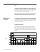
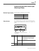
Status Indicators
The 1797-IRT8 module has one status indicator for each input (8 in
all) and one power indicator that is on when power is applied to the
module .
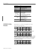
For information on: See page:
Status Indicators 7-1
Repair 7-2
Chapter Summary 7-2
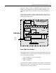
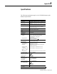
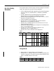
Indicator Color State Meaning
Status Red On At power up – Channel 0 indicator lights at powerup until
all internal diagnostics are checked. After successful
powerup, the indicator goes off if no fault is present.
After successful powerup – Indicates a critical fault
(diagnostic failure, etc.)
Blinking (when
faults are
enabled, and bit
set)
Indicates a noncritical channel fault
Power Off Module not powered
Green On Module receiving power
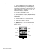
Ex
1797-IRT8
PWR
A B C
A = Status indicators
B = Insertable labels for writing individual input designations
C = Power indicator
40070