
User Manual Owner's manual

Publication 1797-6.5.2 - February 2001
4-14 Input, Status, Output and Configuration Files for the Thermocouple/RTD/mV Module on the ControlNet Network
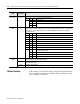
Chapter Summary
In this chapter you learned about input, output and configuration files
for the analog I/O modules on ControlNet. Move to Chapter 5 to learn
how to calibrate your module
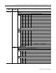
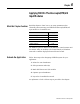
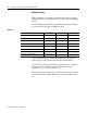
Configuration
Word 1 cont.
Bits 14-15
(16-17)
Input Type Select
Bit 15 14 Input type selection for channels 4-7
0 0 Thermocouple
01RTD
10Not used
11
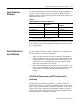
Configuration
Word 2
00-15 (00-17) RTD loop resistance offset select bits – used input type is set to RTD and sensor mode select is set to
2-wire with loop resistance compensation. Allows you to set the type of RTD loop resistance compensation
used for all RTDs or one of three fixed values for all channels. NOTE: Not applicable to 10Ω copper RTD,
which defaults to 0Ω.
Bit 01 00 RTD channel 0
Bit 03 02 RTD channel 1
Bit 05 04 RTD channel 2
Bit 07 06 RTD channel 3
Bit 09 08 RTD channel 4
Bit 11 10 RTD channel 5
Bit 13 12 RTD channel 6
Bit 15 14 RTD channel 7
0 0 Use channel loop compensation value stored during calibration procedure for
2-wire RTD (default = 0Ω)
015Ω
1010Ω
1115Ω
Configuration
Word 3
00-07 Module command data bits – These bits are written to the module during calibration. They are used to
define offset, gain and general channel calibration.
08-14 (10-16) Module command bits – These bits are written to the module during calibration. They are used to select
channel calibration action.
15 (17) Reserved for factory use only.
Configuration
Word
Dec. Bits
(Octal Bits)
Description