
User Manual Owner's manual

Publication 1797-6.5.2 - February 2001
Input, Status, Output and Configuration Files for the Thermocouple/RTD/mV Module on the ControlNet Network 4-13
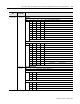
Configuration
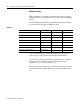
Word 1 cont.
Bits 08-11
(10-13)
Sensor Type (Thermocouple or RTD)
RTD Type
Bit 11 10 09 08 Sensor type for channels 4 through 7
0 0 0 0 Resistance (default)
0 0 0 1 100 ohm Pt α = 0.00385 Euro (–200 to +870°C)
0 0 1 0 200 ohm Pt α = 0.00385 Euro (–200 to +400°C)
0 0 1 1 100 ohm Pt α = 0.003916 U.S. (–200 to +630°C)
0 1 0 0 200 ohm Pt α = 0.003916 U.S. (–200 to +400°C)
0 1 0 1 100 ohm Nickel (–60 to +250°C)
0 1 1 0 200 ohm Nickel (–60 to +200°C)
0 1 1 1 120 ohm Nickel (–80 to +320°C)
1 0 0 0 10 ohm Copper (–200 to +260°C)
1001 through 1111 not used
Thermocouple Type
Bit 11 10 09 08 Sensor type for channels 4 through 7
0 0 0 0 mV (default)
0 0 0 1 B 300 to 1800°C (572 to 3272°F)
0 0 1 0 E –250 to 1000°C (–418 to 1832°F)
0 0 1 1 J –210 to 1200°C (–346 to 2192°F)
0 1 0 0 K –250 to 1372°C (–418 to 2502°F)
0 1 0 1 L –200 to 800°C (–328 to 1472°F)
0 1 1 0 N –250 to 1300°C (–418 to 2372°F)
0 1 1 1 R 0 to 1768°C (32 to 3214°F)
1 0 0 0 S 0 to 1768°C (32 to 3214°F)
1 0 0 1 T –250 to 400°C (–418 to 752°F)
1010 through 1111 not used
Bits 12-13
(14-16)
Sensor Mode Select bits
Bit 13 12 Sensor mode select for channels 4-7
Thermocouple
0 0 CJC compensation – uses cold junction sensor
0 1 Fixed temperature compensation – uses the value selected for reference junction
1 0 No compensation (Data is referenced to 0°C.)
1 1 Differential measurement between 2 channels
RTD
0 0 2-wire RTD no compensation
0 1 2-wire RTD with loop resistance compensation
1 0 3-wire RTD
1 1 4-wire RTD
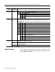
Configuration
Word
Dec. Bits
(Octal Bits)
Description