
User Manual Owner's manual

Publication 1797-6.5.2 - February 2001
4-10 Input, Status, Output and Configuration Files for the Thermocouple/RTD/mV Module on the ControlNet Network
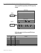
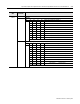
Configuration
Word
Dec. Bits
(Octal Bits)
Description
Configuration
Word 0
Bits 00-02 Input Filter Cutoff bits
Bit 02 01 00 Definition
0 0 0 Hardware filtering only (default filtering)
0 0 1 40Hz (25ms)
0 1 0 10Hz (100ms)
0 1 1 4Hz (250ms)
1 0 0 2Hz (500ms)
1011Hz(1s)
1 1 0 0.5Hz (2s)
1 1 1 0.2Hz (5s)
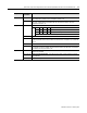
Bits 03-05 Reference Junction – used when input type is set to thermocouple and sensor mode is set to Fixed
Temperature Compensation. Sets a fixed reference junction to compensate all thermocouple channels.
Bit 05 04 03 Reference Junction
0 0 0 0°C
0 0 1 20°C
0 1 0 25°C
0 1 1 30°C
1 0 0 40°C
1 0 1 50°C
1 1 0 60°C
1 1 1 70°C
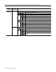
Bits 06-07 Fault Mode bits – when a bit is set (1), fault mode is enabled for that channel. Bit 06 corresponds to
channels 0-3; bit 07 corresponds to channels 4-7.
0 = disabled
1 = enable wire-off detection
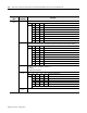
Bits 08-11
(10-13)
Data format – module defaults to –4000 to 10000 in millivolt mode, and 0 to 5000 in ohms mode
Bit 11 10 09 08 Data type for channels 0-7
0000°C
0001°F
0010°K
0 0 1 1 –32767 to +32767
0 1 0 0 0 to 65535
0101 through 1111 not used
Bits 12-15
(14-17)
Not used