
User Manual Owner's manual

Publication 1797-6.5.2 - February 2001
Input, Status, Output and Configuration Files for the Thermocouple/RTD/mV Module on the ControlNet Network 4-5
Adapter Status Word
The status word consists of:
•
I/O module fault bits – 1 status bit for each slot
Additionally, in the case of a PLC-5 controller, it adds:
•
node address changed – 1 bit (created by PLC-5 controller)
•
I/O status – 1 bit (created by PLC-5 controller)
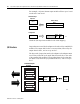
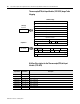
Resulting in the following FLEX Ex adapter status word for a
PLC-5 controller.
As an example, in a PLC-5 system, the adapter status word bit
descriptions are shown in the following table.
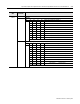
41629
Bit: 15 910 through 15 8 7 6 5 4 3 2 1 0
I/O Module Fault Bits
I/O Status Bit
Node Address Changed Bit
Created by PLC-5 controller
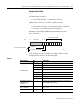
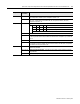
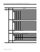
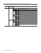
Table 4.A
Bit Description: Bit: Explanation:
I/O Module Fault
0 This bit is set (1) when an error is detected in slot position 0.
1 This bit is set (1) when an error is detected in slot position 1.
2 This bit is set (1) when an error is detected in slot position 2.
3 This bit is set (1) when an error is detected in slot position 3.
4 This bit is set (1) when an error is detected in slot position 4.
5 This bit is set (1) when an error is detected in slot position 5.
6 This bit is set (1) when an error is detected in slot position 6.
7 This bit is set (1) when an error is detected in slot position 7.
Node Address Changed
(Created by PLC-5
controller.)
8 This bit is set (1) when the node address switch setting has
been changed since power-up.
I/O State (Created by
PLC-5 controller.)
9 Bit = 0 -idle
bit = 1 - run
10 though 15 Not used – set to 0