
User Manual Owner's manual


Publication 1797-6.5.2 - February 2001
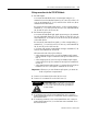
3-12 How to Install Your FLEX Ex Thermocouple/RTD/mV Module
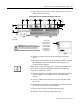
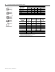
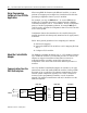
Type of Input
Connect the following:
+HL-
Shield
1
RTD - 2-wire 1 2
RTD - 3-wire 1 3 2
RTD - 4-wire 1 1a 2a 2
Thermocouple 1 2
Millivolt 1 2
1Terminals 16, 33, 40 thru 45 are chassis ground.
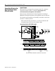
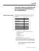
RTD or
Thermocouple
Channel
RTD Source
Current
(+)
High Signal
Terminal (H)
Low Signal
Terminal (L)
Signal
Return
(-)
00123
14567
2891011
312131415
417181920
521222324
625262728
729303132
+V Terminals 34 and 50
-V Terminals 35 and 51
1 Terminals 37, 38 and 39 and 46, 47 and 48 are for cold junction
compensation (with 38 and 47 chassis ground). Connect CJC1 to
terminal 5 or 21, CJC2 to terminal 12 or 29
2 Terminals 16, 33, and 40 thru 45 are chassis ground.
1
2
3
1a
2a
1
2
1
2
1
2
1
2
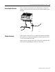
2-wire RTD
3-wire RTD
4-wire RTD
Thermocouple
Millivolt