
User Manual Owner's manual


Publication 1797-6.5.2 - February 2001
2-6 Understanding Configurable FLEX Ex Thermocouple/RTD/mV Input Module Features
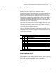
RTD Loop Resistance Offset Select
This parameter is used if Input Type Select is set to RTD and Sensor
Mode Select is set to 2-wire with loop resistance compensation. This
parameter then sets total RTD loop resistance compensation for each
RTD channel. Either the value stored for each channel during
calibration is used to compensate the module RTD channels, or one of
3 fixed values is used to compensate module RTD channels.
This parameter is disabled for Cu10 RTDs.
Range: 0 = use channel loop compensation value determined and
stored during calibration procedure for 2-wire RTD, 1 = 5Ω, 2 = 10Ω,
3= 15Ω. Default = 0.
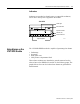
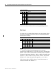
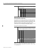
Bits 03-05 Reference Junction – used when input type is set to thermocouple and sensor
mode is set to fixed compensation. Sets a fixed reference junction to compensate
all thermocouple channels.
Bit050403Reference Junction
0000°C
00120°C
01025°C
01130°C
10040°C
10150°C
11060°C
11170°C
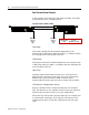
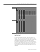
00-15 (00-17) RTD loop resistance offset select bits – used input type is set to RTD and sensor
mode select is set to 2-wire with loop resistance compensation. Allows you to set
the type of RTD loop resistance compensation used for all RTDs or one of three fixed
values for all channels. NOTE: Not applicable to 10W copper RTD, which defaults to
0W.
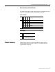
Bit 01 00 RTD channel 0
Bit 03 02 RTD channel 1
Bit 05 04 RTD channel 2
Bit 07 06 RTD channel 3
Bit 09 08 RTD channel 4
Bit 11 10 RTD channel 5
Bit 13 12 RTD channel 6
Bit 15 14 RTD channel 7
0 0 Use channel loop compensation value stored during
calibration procedure for 2-wire RTD (default = 0W)
015W
1 0 10W
1 1 15W