FLEX Ex Thermocouple/ RTD/mV Input Module Cat. No.
Important User Information Because of the variety of uses for the products described in this publication, those responsible for the application and use of this control equipment must satisfy themselves that all necessary steps have been taken to assure that each application and use meets all performance and safety requirements, including any applicable laws, regulations, codes and standards.
Preface Using This Manual Why Read this Manual This manual shows you how to use your FLEX Ex thermocouple/ RTD/mV module with the ControlNet Ex products and ControlNet network. The manual helps you install, program, and troubleshoot your module. Who Should Read this Manual You must be able to program and operate a ControlNet Ex product and ControlNet network to make efficient use of a FLEX Ex module. About the Vocabulary In this manual, we refer to the: • 1797-IRT8 as the “input module”.
Using This Manual 4 For Additional Information For additional information on FLEX Ex systems and modules, refer to the following documents, Publications Catalog Number In Summary Publication 1797-6.5.2 - February 2001 Description Installation Instructions User Manual 1797 Series FLEX Ex Product Data 1797-2.1 (Product data) 1797 Series FLEX Ex System Overview 1797-2.2 (System overview) 1797 Series ControlNet Ex System Cable Guide 1797-6.2.
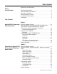
Table of Contents Important User Information . . . . . . . . . . . . . . . . . . . . . . . . . . 2 Preface Using This Manual Why Read this Manual. . . . . . . Who Should Read this Manual . About the Vocabulary . . . . . . . What this Manual Contains . . . For Additional Information . . . In Summary . . . . . . . . . . . . . . . . . . . . . . . . . . . . . . . . . . . . . . . . . . . . . . . . . . . . . . . . . . . . . . . . . . . . . . . . . . . . . . . . . . . . . . . . . . . . . . . . . .
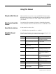
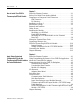
Table of Contents ii Chapter 3 How to Install Your FLEX Ex Thermocouple/RTD/mV Module What this Chapter Contains . . . . . . . . . . . . . . . . . . . Before You Install Your Analog Module. . . . . . . . . . Compliance to European Union Directives . . . . . . . . EMC Directive . . . . . . . . . . . . . . . . . . . . . . . . . . Ex Directive. . . . . . . . . . . . . . . . . . . . . . . . . . . . Installation in Zone 1 . . . . . . . . . . . . . . . . . . . . . . . Electrostatic Charge. . . . . . . . . . .
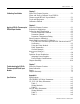
Table of Contents iii Chapter 5 Calibrating Your Module What This Chapter Contains . . . . . . . . . . . When and How to Calibrate Your FLEX Ex Thermocouple/RTD/mV Input Module. . . . Tools and Equipment . . . . . . . . . . . . . . . . Calibration Method . . . . . . . . . . . . . . . . . . . . . . . . . . . . . . 5-1 . . . . . . . . . . . . 5-1 . . . . . . . . . . . . 5-2 . . . . . . . . . . . . 5-2 Chapter 6 Applying FLEX Ex Thermocouple/ RTD/mV Input Modules What this Chapter Contains . . . . . . .
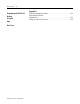
Table of Contents iv Appendix B Programming the FLEX Ex I/O Modules Using RIO Index Back Cover Publication 1797-6.5.2 - February 2001 What this Chapter Contains . . . . . . . . . . . . . . . . . . . . . . . . B-1 Enter Block Transfer Instructions. . . . . . . . . . . . . . . . . . . . . . . . . . . . . . . . . . . . B-1 Using the PLC-5C Processor. . . . . . . . . . . . . . . . . . . . . . . .
Chapter 1 About the FLEX Ex Thermocouple/RTD/mV Input Module What this Chapter Contains Read this chapter to familiarize yourself with the 1797-IRT8 input module. For information on: What the FLEX Ex Thermocouple/RTD/mV Modules Do See page: What the FLEX Ex Thermocouple/ RTD/mV Modules Do 1-1 How FLEX Ex Thermocouple/RTD/mV Modules Communicate with Programmable Controllers 1-2 Features of Your Module 1-2 Chapter Summary 1-5 The 1797-IRT8 module accepts up to 8 thermocouple, RTD or mV inputs.
1-2 About the FLEX Ex Thermocouple/RTD/mV Input Module How FLEX Ex Thermocouple/RTD/mV Modules Communicate with Programmable Controllers FLEX Ex thermocouple/RTD/mV modules provide best utility when used with ControlNet Ex products on the ControlNet network. Data connections are established between the I/O module and an Allen-Bradley programmable controller to transfer information between the two at a scheduled rate. Input module information is then automatically made available in the PLC data table.
About the FLEX Ex Thermocouple/RTD/mV Input Module 1-3 Indicators Indicators are provided to identify input or output fault conditions, and to show when power is applied to the module.
1-4 About the FLEX Ex Thermocouple/RTD/mV Input Module Data Format Alarm Example In this example, the normal active data range is 4-20mA. The alarms are generated in three overlapping bands.
About the FLEX Ex Thermocouple/RTD/mV Input Module 1-5 Data Formats and Fault Modes The tables below shows the bit settings for the data formats and fault modes for your FLEX Ex thermocouple/RTD/mV module.
1-6 About the FLEX Ex Thermocouple/RTD/mV Input Module Publication 1797-6.5.
Chapter 2 Understanding Configurable FLEX Ex Thermocouple/RTD/mV Input Module Features What this Chapter Contains Read this chapter to familiarize yourself with configurable features on the 1797-IRT8 module.
2-2 Understanding Configurable FLEX Ex Thermocouple/RTD/mV Input Module Features Setting a FLEX Ex Thermocouple/RTD Module’s Operating Status Input Type Select Select the thermocouple or RTD mode for input channel groups 0-3 and 4-7. If 2 is selected, the module defaults to thermocouple. If 3 is selected, the module defaults to RTD.
Understanding Configurable FLEX Ex Thermocouple/RTD/mV Input Module Features Bits 00-03 2-3 Sensor Type (Thermocouple or RTD) RTD Type Bit 03 02 01 00 Sensor type for channels 0 through 3 0 0 0 0 Resistance (default) 0 0 0 1 100 ohm Pt α = 0.00385 Euro (–200 to +870°C) 0 0 1 0 200 ohm Pt α = 0.00385 Euro (–200 to +400°C) 0 0 1 1 100 ohm Pt α = 0.003916 U.S. (–200 to +630°C) 0 1 0 0 200 ohm Pt α = 0.003916 U.S.
2-4 Understanding Configurable FLEX Ex Thermocouple/RTD/mV Input Module Features Input Filter Cutoff bits Bit 02 01 00 Definition 0 0 0 Hardware filtering only (default filtering) 600Hz (1.7ms) 0 0 1 40Hz (25ms) 0 1 0 10Hz (100ms) 0 1 1 4Hz (250ms) 1 0 0 2Hz (500ms) 1 0 1 1Hz (1s) 1 1 0 0.5Hz (2s) 1 1 1 0.2Hz (5s) Choose the best input filter cutoff in your programming software. Data Format You must choose a module data format in your user program.
Understanding Configurable FLEX Ex Thermocouple/RTD/mV Input Module Features 2-5 Sensor Mode Select Selects the sensor mode for input channels 0-3 and 4-7. If using cold junction compensation, both CJCs must be installed. The difference between the CJCs will be linearly apportioned to each thermocouple channel based on its position across the base. If one CJC is broken or missing, the remaining CJC is used to compensate all channels. The appropriate CJC alarm will be set in this case.
2-6 Understanding Configurable FLEX Ex Thermocouple/RTD/mV Input Module Features Bits 03-05 Reference Junction – used when input type is set to thermocouple and sensor mode is set to fixed compensation. Sets a fixed reference junction to compensate all thermocouple channels.
Understanding Configurable FLEX Ex Thermocouple/RTD/mV Input Module Features 2-7 Fault Mode Select Select whether the channel fault detection is enabled or disabled for channels 0-3 and 4-7. Range: 0 = disable, 1 = fault detection enabled (wire off, mV overvoltage, RTD open). Default = 0. Bits 06-07 Using Module Alarms Fault Mode bits – when a bit is set (1), fault mode is enabled for that channel. Bit 06 corresponds to channels 0-3; bit 07 corresponds to channels 4-7.
2-8 Understanding Configurable FLEX Ex Thermocouple/RTD/mV Input Module Features IRT8 Specific alarming performance PHYSICAL INPUT SIGNAL RANGE underrange overrange normal signal range CJC fault CJC fault open wire fault Sensor Type IEC PT100 -200C +870C ~ 520ohm equivalent IEC PT200 JIS PT100 JIS PT200 -200C -200C -200C +400C +630C +400C ~ 520ohm equivalent ~ 520ohm equivalent DIN Ni100 DIN Ni200 Minco Ni120 Minco Cu10 0-500 Resistance millivolt B E -60C -60C -80C -200C 0ohm -40mV 300C -25
Understanding Configurable FLEX Ex Thermocouple/RTD/mV Input Module Features 2-9 Fault Alarm The module has individual channel fault alarms for a broken or detached wire. In any mode, if a broken/detached lead is detected, the data value is forced to maximum. Once the alarm is issued, it remains active as long as the input signal is faulted. In mV mode, for input levels above 210mV, this bit is set. In RTD mode, an open input will set this bit.
2-10 Understanding Configurable FLEX Ex Thermocouple/RTD/mV Input Module Features Publication 1797-6.5.
Chapter 3 How to Install Your FLEX Ex Thermocouple/ RTD/mV Module What this Chapter Contains Read this chapter to install the 1797-IRT8 thermocouple/RTD/mV module.
3-2 How to Install Your FLEX Ex Thermocouple/RTD/mV Module Compliance to European Union Directives If this product has the CE mark, it is approved for installation within the European and EEA regions. It has been designed and tested to meet the following directives.
How to Install Your FLEX Ex Thermocouple/RTD/mV Module Electrostatic Charge Removal and Insertion Under Power Protect the system against electrostatic charge. Post a sign near this module: Attention! Avoid electrostatic charge. For your convenience, a sign which can be cut out and posted is included in this user manual before the back cover. ATTENTION ! Installing the Module 3-3 This module is designed so you can remove and insert it under power.
3-4 How to Install Your FLEX Ex Thermocouple/RTD/mV Module 1. Remove the cover plug in the male connector of the unit to which you are connecting this terminal base unit. 2. Check to make sure that the 16 pins in the male connector on the adjacent device are straight and in line so that the mating female connector on this terminal base unit will mate correctly. 3. Make certain that the female flexbus connector is fully retracted into the base unit. 4. Position the terminal base over the 35 x 7.
How to Install Your FLEX Ex Thermocouple/RTD/mV Module 3-5 5. Rotate the terminal base onto the DIN rail with the top of the rail hooked under the lip on the rear of the terminal base. Use caution to make sure that the female flexbus connector does not strike any of the pins in the mating male connector. 41108 Press down on the terminal base unit to lock the terminal base on the DIN rail.
3-6 How to Install Your FLEX Ex Thermocouple/RTD/mV Module Panel/Wall Mounting Installation on a wall or panel consists of: • • • • laying out the drilling points on the wall or panel drilling the pilot holes for the mounting screws mounting the adapter mounting plate installing the terminal base units and securing them to the wall or panel If you are installing your module into a terminal base unit that is already installed, proceed to Mounting the 1797-IRT8 Module on the Terminal Base Unit on page 3-8
How to Install Your FLEX Ex Thermocouple/RTD/mV Module 3-7 1. Lay out the required points on the wall/panel as shown in the drilling dimension drawing. Drilling Dimensions for Panel/Wall Mounting of FLEX Ex I/O 1.4 (35.5) 2.3 (58.5) 1.4 (35.5) 2.3 (58.5) 1.4 (35.5) 1.6 (40.5) .61 (15.6) .3 (8) .83 (21) 2.0 (50) Inches (Millimeters) ! ATTENTION: Be careful of metal chips when drilling cable mounting holes. Do not drill holes above a system that has any modules installed.
3-8 How to Install Your FLEX Ex Thermocouple/RTD/mV Module Mounting the 1797-IRT8 Module on the Terminal Base Unit The 1797-IRT8 module mounts on a 1797-TB3 or TB3S intrinsically safe terminal base unit. 1. Rotate keyswitch (1) on terminal base unit (2) clockwise to position 2 as required for this type of module. Do not change the position of the keyswitch after wiring the terminal base unit. 7 3 1 8 2 6 4 5 40231 Label under here or under here 2.
How to Install Your FLEX Ex Thermocouple/RTD/mV Module 3-9 6. Make certain that you only connect terminal base units to other intrinsically safe system modules or adapters to maintain the integrity of the intrinsically-safe backplane. 7. Remove cap plug (8) and attach another intrinsically safe terminal base unit to the right of this terminal base unit if required. Make sure the last terminal base has the cap plug (8) in place. 41307 The adapter is capable of addressing eight modules.
3-10 How to Install Your FLEX Ex Thermocouple/RTD/mV Module Connecting Wiring to the FLEX Ex Thermocouple/ RTD/mV Module Inputs/Outputs Each input can be operated from a thermocouple (TC), resistance temperature detector (RTD), or millivolt. Do not apply any non-intrinsically safe signals to this module. When using an intrinsically safe electrical apparatus according to EN50020, the European directives and regulations must be followed.
How to Install Your FLEX Ex Thermocouple/RTD/mV Module 3-11 Wiring connections for the 1797-IRT8 Module 1. For RTD inputs: a. connect the individual source current input wiring to (+) terminals for each individual channel (0, 4, 8 and 12) on the 0-15 row (A) and terminals 17, 21, 25, and 29 on the 16-33 row (B) as indicated in the table below. b.
3-12 How to Install Your FLEX Ex Thermocouple/RTD/mV Module 1 2 2-wire RTD 1 3 2 Type of Input Connect the following: + H L RTD - 2-wire RTD - 3-wire RTD - 4-wire Thermocouple Millivolt 1 1 1 2 2 2 2 2 3 2a 1 1 1a Shield1 1Terminals 16, 33, 40 thru 45 are chassis ground.
How to Install Your FLEX Ex Thermocouple/RTD/mV Module Grounding the Module 3-13 All I/O wiring must use shielded wire. Shields must be terminated external to the module, such as bus bars and shield-terminating feed throughs. 30820-M Chapter Summary In this chapter, we told you how to install your thermocouple/RTD/ mV module in an existing programmable controller system and how to wire to the terminal base units.
3-14 How to Install Your FLEX Ex Thermocouple/RTD/mV Module Publication 1797-6.5.
Chapter 4 Input, Status, Output and Configuration Files for the Thermocouple/RTD/mV Module on the ControlNet Network What this Chapter Contains Read this chapter to familiarize yourself with input, output and configuration files for the thermocouple/RTD/mV module on ControlNet.
4-2 Input, Status, Output and Configuration Files for the Thermocouple/RTD/mV Module on the ControlNet Network Using Programming Software in Your FLEX Ex Application When using FLEX Ex thermocouple/RTD/mV modules, you must perform I/O mapping and configure the ControlNet network before generating configuration data for your I/O modules. For example, you may use RSNetWorx™ to connect FLEX Ex I/O modules to a ControlNet processor or scanner through a FLEX Ex ControlNet Ex adapter (cat. no. 1797-ACNR15).
Input, Status, Output and Configuration Files for the Thermocouple/RTD/mV Module on the ControlNet Network 4-3 Scheduled Data-Transfer Scheduled data transfer: • is continuous. • is asynchronous to the controller program scan.
4-4 Input, Status, Output and Configuration Files for the Thermocouple/RTD/mV Module on the ControlNet Network For example, a 16 point discrete input module will have up to 2 read words and 1 write word. ControlNet Image Input Size Module Image 1 Word Input Status Size Faults 1 Word Configuration 1 Word Not used Delay Time Delay Time 41627 Check the I/O map for the module for the exact mapping. I/O Structure Output data is received by the adapter in the order of the installed I/O modules.
Input, Status, Output and Configuration Files for the Thermocouple/RTD/mV Module on the ControlNet Network 4-5 Adapter Status Word The status word consists of: • I/O module fault bits – 1 status bit for each slot Additionally, in the case of a PLC-5 controller, it adds: • node address changed – 1 bit (created by PLC-5 controller) • I/O status – 1 bit (created by PLC-5 controller) Resulting in the following FLEX Ex adapter status word for a PLC-5 controller.
4-6 Input, Status, Output and Configuration Files for the Thermocouple/RTD/mV Module on the ControlNet Network Possible causes for an I/O Module Fault are: • • • • • • transmission errors on the FLEX Ex backplane a failed module a module removed from its terminal base incorrect module inserted in a slot position the slot is empty the slot contains a non-discrete module Fault State Data The ControlNet Ex adapter provides storage for alternate module output data during communication faults or processor i
Input, Status, Output and Configuration Files for the Thermocouple/RTD/mV Module on the ControlNet Network 4-7 Idle State Behavior The ControlNet Ex adapter can detect the state of the controlling processor or scanner. Only 2 states can be detected: – run mode, – or program mode (idle). When run mode is detected, the adapter copies the output data received from the processor to the corresponding module output.
4-8 Input, Status, Output and Configuration Files for the Thermocouple/RTD/mV Module on the ControlNet Network Thermocouple/RTD/mV Input Module (1797-IRT8) Image Table Mapping Module Image Input Data Channel 0 Input Data Channel 1 I/O Image Input Data Channel 2 Input Size Input Data Channel 3 1 to 11 Words Input Data Channel 4 Input Data Channel 5 Input Data Channel 6 Input Data Channel 7 Overrange Underrange Alarms Output Size RFlg Diagnostics Module command and response 0 to 4 Words TC/RTD CJC
Input, Status, Output and Configuration Files for the Thermocouple/RTD/mV Module on the ControlNet Network Input Word Dec. Bits (Octal Bits) Input Word 8 00-07 08-15 (10-17) Input Word 9 00-03 4-9 Description Underrange bits – these bits are set if the input signal is below the input channel’s minimum range. Bit 00 corresponds to channel 0, bit 01 corresponds to channel 1, etc.
4-10 Input, Status, Output and Configuration Files for the Thermocouple/RTD/mV Module on the ControlNet Network Configuration Word Dec. Bits (Octal Bits) Configuration Word 0 Bits 00-02 Description Input Filter Cutoff bits Bit Bits 03-05 02 01 00 Definition 0 0 0 Hardware filtering only (default filtering) 0 0 1 40Hz (25ms) 0 1 0 10Hz (100ms) 0 1 1 4Hz (250ms) 1 0 0 2Hz (500ms) 1 0 1 1Hz (1s) 1 1 0 0.5Hz (2s) 1 1 1 0.
Input, Status, Output and Configuration Files for the Thermocouple/RTD/mV Module on the ControlNet Network Configuration Word Dec. Bits (Octal Bits) Configuration Word 1 Bits 00-03 4-11 Description Sensor Type (Thermocouple or RTD) RTD Type Bit 03 02 01 00 Sensor type for channels 0 through 3 0 0 0 0 Resistance (default) 0 0 0 1 100 ohm Pt α = 0.00385 Euro (–200 to +870°C) 0 0 1 0 200 ohm Pt α = 0.00385 Euro (–200 to +400°C) 0 0 1 1 100 ohm Pt α = 0.003916 U.S.
4-12 Input, Status, Output and Configuration Files for the Thermocouple/RTD/mV Module on the ControlNet Network Configuration Word Dec. Bits (Octal Bits) Configuration word 1 cont. Bits 04-05 Description Sensor Mode Select bits Bit 05 04 Sensor mode select for channels 0-3 0 0 CJC compensation – uses cold junction sensor 0 1 Fixed Temperature compensation – uses the value selected for reference junction 1 0 No compensation (Data is referenced to 0°C.
Input, Status, Output and Configuration Files for the Thermocouple/RTD/mV Module on the ControlNet Network Configuration Word Dec. Bits (Octal Bits) Configuration Word 1 cont. Bits 08-11 (10-13) 4-13 Description Sensor Type (Thermocouple or RTD) RTD Type Bit 11 10 09 08 Sensor type for channels 4 through 7 0 0 0 0 Resistance (default) 0 0 0 1 100 ohm Pt α = 0.00385 Euro (–200 to +870°C) 0 0 1 0 200 ohm Pt α = 0.00385 Euro (–200 to +400°C) 0 0 1 1 100 ohm Pt α = 0.003916 U.S.
4-14 Input, Status, Output and Configuration Files for the Thermocouple/RTD/mV Module on the ControlNet Network Configuration Word Dec. Bits (Octal Bits) Configuration Word 1 cont.
Chapter 5 Calibrating Your Module What This Chapter Contains Use this chapter to calibrate the thermocouple/RTD/mV input module. We tell you about: For information on See page When and How to Calibrate Your TC/RTD Module. . . . . . . . . . . . . . . . 5-1 Tools and Equipment . . . . . . . . . . . . . . . . . . . . . . . . . . . . . . . . . . . . . 5-2 Calibration Method 5-2 When and How to Calibrate Your FLEX Ex Thermocouple/RTD/mV Input Module Your module is shipped to you already calibrated.
5-2 Calibrating Your Module Tools and Equipment Calibration Method To calibrate your analog I/O modules, you will need the following tools and equipment: Tool or Equipment: Description: Precision Resistors High precision resistors: 383W, 0.01%, 5ppm/oC 100W, 0.01%, 5ppm/oC 10kW, 0.
Chapter 6 Applying FLEX Ex Thermocouple/RTD/mV Input Modules What this Chapter Contains Read this chapter to learn how to use entity parameters when electrically interconnecting your FLEX Ex thermocouple/RTD/mV input module in a hazardous area.
6-2 Applying FLEX Ex Thermocouple/RTD/mV Input Modules Define the Area Classification Before you can determine what components will make up your FLEX Ex system, you must define the area in which that system will operate. You must determine the following: • classification method • hazard • temperature rating Decide Classification Method Your application location will usually decide whether the classification method is Zone or Class/Division, but the system designer may make this determination.
Applying FLEX Ex Thermocouple/RTD/mV Input Modules Select Protection Method(s) 6-3 The following table shows protection methods, method designation, and how each provides protection. Although the FLEX Ex system primarily uses the Intrinsic Safety protection method, the system uses all methods listed below. Table 6.
6-4 Applying FLEX Ex Thermocouple/RTD/mV Input Modules Similarly for RTDs an number of industry standard types are available, such as PT100, Ni100, etc. Again, the IRT8 is designed to work with a variety of these types. Functional compatibility is simply a matter of selecting the correct sensor type when configuring the IRT8 module with the system I/O configuration software. Thermocouples and RTDs are known as “simple devices” from an IS standpoint.
Applying FLEX Ex Thermocouple/RTD/mV Input Modules 6-5 Total Loop column, in the manner shown. The values in the Total Loop column are determined in the following manner: • Total Loop Ui is equal to the transmitter Ui. • Total Loop Ii is equal to the transmitter Ii. • Total Loop Ci is the addition of the transmitter Ci and the cabling Ci per length multiplied by the cable length. • Total Loop Li is the addition of the transmitter Li and the cabling Li per length multiplied by the cable length.
6-6 Applying FLEX Ex Thermocouple/RTD/mV Input Modules Entity Parameters Entity parameters are a system of quantified safe levels for voltage, current, inductance, and capacitance used when connecting multiple devices. The following table details the entity parameters that must be taken into account when designing a FLEX Ex system. Table 6.
Applying FLEX Ex Thermocouple/RTD/mV Input Modules 6-7 General Example Entity parameters allow a user to design an instrumentation loop by selecting entities such as I/O, wiring and field devices that meet parameters defined by local manufacturers and certifying agencies. For example, a user may have an input channel and a transmitter sending that channel information.
6-8 Applying FLEX Ex Thermocouple/RTD/mV Input Modules I/O The 1797-IRT8 module complies fully to and provides simple entity parameters. This module can directly interface with a wide variety of intrinsically safe controls and instrumentation. Because all field device power is supplied directly from the I/O module, no extra wiring or power sources are needed in a hazardous area.
Applying FLEX Ex Thermocouple/RTD/mV Input Modules 6-9 Each power supply output in the FLEX Ex system is rated for 8.5W. Modules can be attached to the output until their combined power equals that number. Do not exceed the power supply maximum of 8.5W. Assign the next module to another output as before. When all four power supply outputs are utilized, add another power supply to the system, see the figure below.
6-10 Applying FLEX Ex Thermocouple/RTD/mV Input Modules Chapter Summary Publication 1797-6.5.2 - February 2001 In this chapter you learned how to troubleshoot the FLEX Ex analog I/O modules. Move to chapter 6 to learn about troubleshooting your modules.
Chapter 7 Troubleshooting the FLEX Ex Thermocouple/ RTD/mV Input Module What this Chapter Contains Read this chapter to troubleshoot your I/O module. For information on: Status Indicators See page: Status Indicators 7-1 Repair 7-2 Chapter Summary 7-2 The 1797-IRT8 module has one status indicator for each input (8 in all) and one power indicator that is on when power is applied to the module .
7-2 Troubleshooting the FLEX Ex Thermocouple/RTD/mV Input Module Repair This module is not field repairable. Any attempt to open this module will void the warranty and IS certification. If repair is necessary, return this module to the factory. Chapter Summary In this chapter you learned how to troubleshoot the FLEX Ex thermocouple/RTD/mV module. Move to Appendix A to see the specifications for your module. Publication 1797-6.5.
Appendix A Specifications The following specifications apply to the 1797-IRT8 thermocouple/ RTD/mV input module.
A-2 Specifications Power Dissipation Thermal Dissipation Module Location Conductor Wire Size Dimensions Weight Keyswitch Position Environmental Conditions Operational Temperature Storage Temperature Relative Humidity Shock Operating Nonoperating Vibration Agency Certification CENELEC UL/C-UL FM Certificate of Conformity CE/CENELEC I/O Entity Parameters 1.6W Maximum 5.46BTU/hr Cat. No. 1797-TB3 or -TB3S Terminal Base Unit 12 gauge (4mm2) stranded maximum 3/64in (1.
Specifications UL, C-UL I/O Entity Parameters A-3 If the product has the UL/C-UL mark, it has been designed, evaluated, tested, and certified to meet the following standards: • UL 913, 1988, Intrinsically Safe Apparatus and Associated Apparatus for use in Class I, II, and III Division 1, Hazardous (Classified) Locations • UL 1203, Explosion-Proof and Dust-Ignition-Proof Electrical Equipment for Use in Hazardous (Classified) Locations • UL 2279, Electrical Equipment for Use in Class I, Zone 0, 1, and 2 Ha
A-4 Specifications The entity concept allows interconnection of intrinsically safe apparatus with associated apparatus not specifically examined in combination as a system when the approved values of Vt and It of the associated apparatus are less than or equal to Voc and Isc or Vmax and Imax of the intrinsically safe apparatus and the approved values of Ca and La of the associated apparatus are greater than Ci + Ccable and Li + Lcable respectively for the intrinsically safe apparatus.
Specifications Hazardous (Classified) Location Class I, Zones 0, 1, & 2 Groups IIC, IIB, IIA Class I, Div. 1 & 2 Groups A, B, C, D Class II, Div. 1 & 2 Groups E, F, G Class III, Div. 1 & 2 ó A-5 Hazardous (Classified) Location Class I, Zones 1 & 2 Groups IIC, IIB, IIA Class I, Div. 1 & 2 Groups A, B, C, D Any Simple Apparatus or I.S. device with Entity Concept parameters (Vmax, Imax, Ci, Li) appropriate for connection to associated apparatus with Entity Concept parameters listed in Table 1.
A-6 Specifications Wiring Methods • Wiring method 1 - Each channel is wired separately. • Wiring method 2 - Multiple channels in one cable, providing each channel is separated in accordance with the National Electric Code (NEC). Table 1 Wiring Method 1 and 2 Channel Terminals Any one 0(+), 1(H), 2(L), channel e.g. 3(-) ch0 Voc (V) Isc (mA) Vt (V) It (mA) Groups Ca (µF) La (mH) 9.0 37.0 - - A, B 3.0 20.0 37, 38, 39 (CJC0) or 46, 47, 48 (CJC1) 9.
Specifications A-7 AVERTISSEMENT: La substitution de composant peut compromettre la securite intrinseque. FLEX Ex Temperature Input I/O Module A- B Allen-Bradley 1797- IRT8 8 Point RTD/Thermocouple mV Input Module 2 0 1 2 3 4 5 6 7 Key Position for Terminal Base Insertion PWR LEDs Male Bus Connection Female Bus Connection Terminal Base Key Field Wiring Terminals Terminal Bas 42020 ATTENTION A terminal base may or may not have an I/O module installed. ! Publication 1797-6.5.
A-8 Specifications Hazardous (Classified) Location Class I, Zone 0 Group IIC Class I, Div. 1 Groups A, B, C, D Class II, Div. 1 Groups E, F, G Class III, Div. 1 ó Hazardous (Classified) Location Class I, Zone 1 Group IIC Class I, Div. 1 Groups A, B, C, D Any Simple Apparatus or FM approved device with Entity Concept parameters (Vmax, Imax, Ci, Li) appropriate for connection to associated apparatus with Entity Concept parameters listed in Table 1.
Appendix B Programming the FLEX Ex I/O Modules Using RIO What this Chapter Contains Read this appendix to program the 1797-IRT8 thermocouple/RTD/mV input module. Enter Block Transfer Instructions The FLEX Ex thermocouple/RTD/mV modules communicate with the PLC processor through bidirectional block transfers. This is the sequential operation of both read and write block transfer instructions. Before you configure the module, you need to enter block transfer instructions into your ladder logic.
B-2 Programming the FLEX Ex I/O Modules Using RIO Using the PLC-5C Processor Block transfer instructions with the PLC-5C processor use a control file and a data file. The block transfer control file contains the data table section for module location, the address of the block transfer data file and other related data. The block transfer data file stores data that you want transferred to the module (when programming a BTW) or from the module (when programming a BTR).
Index Numerics CE/CENELEC 1797-IRT8 A-5 1797-IRT8 entity parameters UL 1797-IRT8 A-5 CE/CENELEC A-5 UL A-5 I A Alarms 1797-IE8 module 1-3 inputs 1-1 installation module 3-8 local fault 1-3 overrange 1-3 remote fault 1-3 underrange 1-3 module shipping state B calibration 5-1 module installation 3-8 block transfer programming PLC5/250 processor B-2 M mounting on terminal base 3-8 mounting kit cat. no.
2 Index Publication 1797-6.5.
Allen-Bradley Publication Problem Report If you find a problem with our documentation, please complete and return this form. Pub. Name FLEX Ex Thermocouple/RTD/mV Module User Manual Cat. No. 1797-IRT8 Check Problem(s) Type: Pub. No. 1797-6.5.2 Pub. Date February 2001 Part No.
PLEASE FASTEN HERE (DO NOT STAPLE) PLEASE FOLD HERE NO POSTAGE NECESSARY IF MAILED IN THE UNITED STATES BUSINESS REPLY MAIL FIRST-CLASS MAIL PERMIT NO.
Attention: Avoid electrostatic charge. Attention: Avoid electrostatic charge. Attention: Avoid electrostatic charge. Attention: Avoid electrostatic charge. Attention: Avoid electrostatic charge.
Publication 1797-6.5.2 - February 2001 PN 955126-46 © (2001) Rockwell International Corporation. Printed in the U.S.A.