
Installation Instruction User Manual

4
Publication 1794-IN067C-EN-P - January 2012
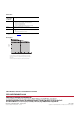
Status Indicators
This module has one red/green power/status indicator (OK), and one yellow
indicator for each input and output. The I/O status indicators are multiplexed
in 2 groups (A0, B0, Z0, O0, O1); and (A1, B1, Z1, O2, O3) at a frequency of
488
Hz. If inputs or outputs change at or near that frequency, the indicators
will vary in brightness.
When an active indicator (yellow) is lighted, a valid signal (active high or active low)
is present at the input terminals.
The module power/status indicator (OK) shows power applied to the module, and
the status of the module.
Diagnostic Codes Returned by the Module
If an incomplete, incorrect or conflicting set of configuration parameters is sent to
the module, the PE bit is asserted, the green module status indicator flashes, and an
error code is displayed in bits 0…11 of the module/channel status word. The codes
are identified below. Use a CIO instruction to access this information.
During hardware self-tests, when either FlexBus power or terminal base power is
first applied and a fatal error occurs, the TF bit is asserted and the red
module/power status indicator comes on. An error code is placed in the lower byte
of the module/channel status word to indicate the failed resource. Use a CIO
instruction to access this information. When using the CIO instruction, this would
be word 10.
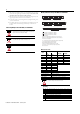
0 Z
F
B
F
AF Filter Description
0 0 0 0 No filter
0 0 0 1 50 kHz (10 μs + 0 μs/-1.6 μs)
0 0 1 0 5k Hz (100 μs + 0 μs/-13.2 μs)
0 1 0 0 500 Hz (1.0 ms + 0 ms/-125 μs)
1 0 0 0 50 Hz (10.0 ms + 0 ms/-1.25 ms)
0 A input not filtered
1 A input filtered
0 B input not filtered
1 B input filtered
0 Z input not filtered
1 Z input filtered
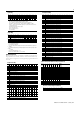
Status Indicators
Indicator Indication Explanation
A (status of input A Yellow Input A active
Off Input A not active
B (status of input B Yellow Input B active
Off Input B not active
Z (status of input Z Yellow Input Z active
Off Input Z not active
Out 0, 1, 2, 3 Yellow Output is on
Off Individual output is off
Indicator Indication Explanation
OK Solid red • Hardware diagnostic error, TF set to 1 and
module/channel status contains error code
• Hardware runtime failure (that is, watchdog
timeout), module communication ceases
Flashing red • Module is configuring hardware, NR is set to 1.
• Module is in test mode (bits 8…15 of counter
control word are nonzero), TF set to 1
Flashing red
(with occasional
flashing green)
• Module 24V power is below minimum rating.
Solid green • Module is active and acting normally
Flashing green • Module is not configured
• Programming error, PE is set to 1 and error code
is supplied in bits 0…11 of module/channel
status word
• Field power fault, FP set to 1
• Adapter powered down, and module local
power still active
• ControlNet cable disconnected
• PLC in PROG mode
Filter Selection (Configuration Word 1)
VERY
HIGH SPEED COUNTER MODULE
1794-VHSC
ABZ ABZ
Allen-Bradley
1OUT
01 23
OUT0
A
B
A = Status Indicators
B = Power Indicator
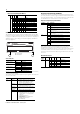
Diagnostics Reported by Input Data Word 8
Read Word
Bit Indication
Word 8 00 A reserved configuration or mode was programmed.
01 ZF/BF/AF were selected and no filter was programmed, or multiple filters were
selected.
02 A timebase was entered that was not a multiple of 10, or the timebase is out of
range (>3000, that is 3 s).
03 A configuration requiring a timebase was selected and no gate interval was set,
or the gate interval is out of range (>3
s) or the product of timebase and gate
interval is greater than 3
s.
04 A rollover of zero was programmed through PWM was not selected; a rollover
was programmed and PWM was selected; or the rolloveris out of range (1 <
rollover < 16,777,216).
Word 05 The preset (1 < preset < 16,777,216) is out of range.
06 A configuration was selected that requires a scalar, and no scalar was
programmed or multiple scalars were selected.
07 A tie has been connected to an unprogrammed window.
08 Counter 0 window ON and OFF values are equal and not zero or counter 0
window ON and OFF value greater than16,777,215.
09 Counter 1 window ON and OFF values are equal and not zero or counter 1
window ON and OFF value greater than16,777,215.
10 Reserved
11
Word 9 Bit Description
Read
Word
Bit 02 01 00 Dec. Definition
Word 8 00…07 0 0 1 1 RAM test failed
0 1 0 2 ROM checksum test failed
0 1 1 3 EEPROM test failed
1 0 0 4 Programmable Gate Array
loading failed
All other combinations not used