
Installation Instruction User Manual

3
Publication 1794-IN067C-EN-P - January 2012
Configuration Image
When a configuration is sent to the module, it is checked for consistency before
being applied. If an error is found, the PE bit is asserted and the module locally
retains its previous configuration. Your user application program should monitor
the PE bit.
7 Channel 1 Stored/AccumulatedCount (most significant word)
8 PE FP NR TF OS 3 OS 2 OS 1 OS 0 C1 C0 ZF ZS C1 C0 ZF ZS
Where:PE = Programming error (error code in bits 11:0)
FP = Field power (24V DC power lost)
NR = Not ready (configuring field programmable array FPGA)
TF = Test fail flag = 1 (indicating failure during powerup) red indicator on.
Code in bits 2:0 indicate fail code (1 = RAM; 2 = ROM; 3 = EEPROM; 4 = FPGA)
Test flag = 1 with red indicator blinking, upper byte of counter control word in non-zero
– in production test mode.
OS = Output status (current state of output)
C1, C0 = Stored data count
ZF = Zero frequency detected
ZS = Z input status
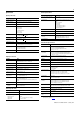
Output Map
Dec 15 14 13 12 11 10 9 8 7 6 5 4 3 2 1 0
Oct 17 16 15 14 13 12 11 10 7 6 5 4 3 2 1 0
0 Reserved for test 0 VR1 CP1 CR1 0 VR0 CP0 CR0
1 0 LC3 OE3 FO3 0 LC2 OE2 FO2 0 LC1 OE1 FO1 0 LC0 OE0 FO0
2 Channel 0 PWM Output Value (0-95.00%)
3 Channel 1 PWM Output Value (0-95.00%)
Where:VR = Value reset of stored/accumulated count (channel)
CP = Counter preset (channel)
CR = Counter reset (channel)
LC = Local control (channel) - outputs remain under control when FlexBus is unpowered -
1 = enabled
OE = Output enable (channel) - permitting output to be turned on from FO, compare match
or PWM
- 1 = enabled
FO = Forced output (channel) - 1 = on
PWM = Pulse width modulation (0…9500 decimal)
Configuration Map
Dec 15 14 13 12 11 10 9 8 7 6 5 4 3 2 1 0
Oct 17 16 15 14 13 12 11 10 7 6 5 4 3 2 1 0
0 Counter Configuration
1 Filter Selection
2 Time Base Value/PWM Period
3 Channel 0 Gate Interval
4 Channel 1 Gate Interval
5 Reserved
6 Channel 0 Rollover Value (least significant word)
7 Channel 0 Rollover Value (most significant word)
8 Channel 1 Rollover Value (least significant word)
9 Channel 1 Rollover Value (most significant word)
10 Channel 0 Preset Value (least significant word)
11 Channel 0 Preset Value (most significant word)
12 Channel 1 Preset Value (least significant word)
13 Channel 1 Preset Value (most significant word)
14 Channel 0 Scaler
15 Channel 1 Scaler
16 0 0 0 0 0 0 0 0 S
4
S
3
S
2
S
1
F
4
F
3
F2 F
1
17 0 0 0 0 0 0 0 0 S
4
S
3
S
2
S
1
F
4
F
3
F2 F
1
18 0 0 0 0 0 0 0 0 S
4
S
3
S
2
S
1
F
4
F
3
F2 F
1
19 0 0 0 0 0 0 0 0 S
4
S
3
S
2
S
1
F
4
F
3
F2 F
1
20 First Counter 1st ON Value (least significant word)
21 First Counter 1st ON Value (most significant word)
Input Map
Dec. 15 14 13 12 11 10 9 8 7 6 5 4 3 2 1 0
Oct. 17 16 15 14 13 12 11 10 7 6 5 4 3 2 1 0
22 First Counter 1st OFF Value (least significant word)
23 First Counter 1st OFF Value (most significant word)
24 First Counter 2nd ON Value (least significant word)
25 First Counter 2nd ON Value (most significant word)
26 First Counter 2nd OFF Value (least significant word)
27 First Counter 2nd OFF Value (most significant word)
28 First Counter 3rd ON Value (least significant word)
29 First Counter 3rd ON Value (most significant word)
30 First Counter 3rd OFF Value (least significant word)
31 First Counter 3rd OFF Value (most significant word)
32 First Counter 4th ON Value (least significant word)
33 First Counter 4th ON Value (most significant word)
34 First Counter 4th OFF Value (least significant word)
35 First Counter 4th OFF Value (most significant word)
36 Second Counter 1st ON Value (least significant word)
37 Second Counter 1st ON Value (most significant word)
38 Second Counter 1st OFF Value (least significant word)
39 Second Counter 1st OFF Value (most significant word)
40 Second Counter 2nd ON Value (least significant word)
41 Second Counter 2nd ON Value (most significant word)
42 Second Counter 2nd OFF Value (least significant word)
43 Second Counter 2nd OFF Value (most significant word)
44 Second Counter 3rd ON Value (least significant word)
45 Second Counter 3rd ON Value (most significant word)
46 Second Counter 3rd OFF Value (least significant word)
47 Second Counter 3rd OFF Value (most significant word)
48 Second Counter 4th ON Value (least significant word)
49 Second Counter 4th ON Value (most significant word)
50 Second Counter 4th OFF Value (least significant word)
51 Second Counter 4th OFF Value (most significant word)
52 Counter Control Safe State
53 Output Control Safe State
54 Channel 0 PWM Safe State
55 Channel 1 PWM Safe State
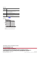
Counter Configuration/Mode (Configuration Word 0)
Bit 7 6 5 4 3 2 1 0 Counter 0
Bit 15 14 13 12 11 10 9 8 Counter 1
Mode Configuration Description
0 0 0 0 Counter
0 0 0 1 Encoder X1
0 0 1 0 PWM
0 1 0 0 Encoder X4
0 1 0 1 Period/Rate
0 1 1 0 Continuous/Rate
0 1 1 1 Rate Measurement
0 0 0 Store Count Disabled
0 0 1 Mode 1 – Store/Continue
0 1 0 Mode 2 – Store; Reset/Resume
0 1 1 Mode 3 – Store; Reset/Wait/Start
1 0 0 Mode 4 – Store; Reset/start
110 and 111 Reserved
0 Z input not inverted
1 Z input inverted
Filter Selection (Configuration Word 1)
Bit 7 6 5 4 3 2 1 0 Counter 0
Bit 15 14 13 12 11 10 9 8 Counter 1
Configuration Map
Dec1514131211109 8 7 6 5 4 3 2 1 0
Oct 17161514131211107 6 5 4 3 2 1 0