
User Manual User Manual


50 Rockwell Automation Publication 1794-UM010D-EN-E - July 2013
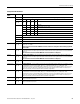
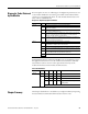
Specifications
Current, on-state, max 5V DC terminations: 0.5 A
12…24V DC terminations: 1.0 A
Current per
output pair, max
5V DC terminations: 0.5 A
12…24V DC terminations: 1.0 A
Short circuit current 5V DC terminations: 0.9A
12…24V DC terminations: 4.0A
Outputs are short-circuit protected and turned off until power is cycled.
Surge current 2A for 50 ms, repeatable every 2 s
Delay Time
Off to On
On to Off
25 μs (load dependent)
150 μs (load dependent)
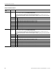
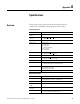
General Specifications
Attribute Value
Module location 1794-TB3G and 1794-TB3GS
External DC power supply
voltage range, nom
24V DC
Supply voltage 19.2…31.2V DC (includes 5% AC ripple)
Supply current 100 mA @ 24V DC
Dimensions, HxWxD
(with module installed on
terminal base)
94 x 94 x 69 mm
(3.7 x 3.7 x 2.7 in.)
Isolation voltage 50V (continuous), Basic Insulation Type, between six isolated areas
including:
FlexBus
Module 24V DC power
A0/B0/Z0 inputs
A1/B1/Z1 inputs
00/01 and output power supply 1
02/03 and output power supply 2
Tested @ 850V DC for 1 s
FlexBus current 75 mA @ 5V DC (with terminal base power off)
Power dissipation, max 5.0 W @ 31.2V DC
Thermal dissipation, max 17.1 BTU/hr @ 31.2V DC
Indicators
(field side driven, logic
side indication)
1 green/red power/status indicator
6 yellow input status indicators – logic side
4 yellow output tatus indicators – logic side
Keyswitch position 1
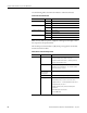
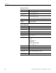
Output Specifications
Attribute Value