
User Manual User Manual


48 Rockwell Automation Publication 1794-UM010D-EN-E - July 2013
Interpret Status Indicators for your FLEX I/O Module
Use the following table to determine the indicator conditions and status.
When an active indicator (yellow) is lighted, a valid signal (active high or active
low) is present at the input terminals.
The module power/status indicator (OK) shows power applied to the module,
and the status of the module.
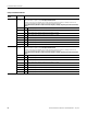
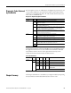
Status Indicator Identification
Indicator State Status
A (status of input A) Yellow Input A active.
Off Input A not active.
B (status of input B) Yellow Input B active.
Off Input B not active.
Z (status of input Z) Yellow Input Z active.
Off Input Z not active.
Out O, 1, 2, 3 Yellow Output is on.
Off Individual output is off.
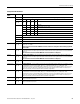
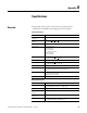
Power/Status Indicator Interpretation
Indicator State Status
OK Solid red • Hardware diagnostic error, TF set to 1 and
module/channel status contains error code.
• Hardware runtime failure (that is, watchdog timeout),
module communication ceases.
Flashing red • Module is configuring hardware, NR is set to 1.
• Module is in test mode (bits 8…15 of counter control
word are nonzero), TF set to 1.
Flashing red
(with occasional
flashing green)
Module 24V power is below minimum rating.
Solid green Module is active and acting normally.
Flashing green • Module is not configured.
• Programming error, PE is set to 1 and error code is
supplied in bits 0…11 of module/channel status word.
• Field power fault, FP set to 1.
• Adapter powered down, and module local power
still active.
• ControlNet cable disconnected.
• PLC in PROG mode.