
User Manual User Manual


Rockwell Automation Publication 1794-UM010D-EN-E - July 2013 43
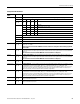
Communicate With Your Module
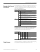
Word 1 Filter Selection – Only 1 filter selection can be chosen at a time. Frequency = 50% duty cycle.
Bits 00…03 03 02 01 00 Counter 0
Bits 08…11
(10…13)
11
(13)
10
(12)
09
(11)
08
(10)
Counter 1
000 0No filter
0 0 0 1 50 kHz (10 μs + 0 μs/-1.6 μs)
0 0 1 0 5 kHz (100 μs + 0 μs/-13.2 μs)
0 1 0 0 500 Hz (1.0 ms + 0 ms/-1.25 μs)
1 0 0 0 50 Hz (10.0 ms + 0 ms/-1.25 ms)
Bit 12 (14) Input A filter bit (AF) – 0 = not filtered; 1 = apply filter to input
Bit 13 (15) Input B filter bit (BF) – 0 = not filtered; 1 = apply filter to input
Bit 14 (16) Input Z filter bit (ZF) – 0 = not filtered; 1 = apply filter to input
Bit 15 (17) Set to 0.
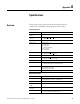
Word 2 Bits 00…15
(00…17)
Time base – Sets the fundamental time base for both counters. Resolution in ms, with a minimum of 10 ms intervals
(10 ms = 10; 1 s = 1000).
Time base must be entered when PWM and rate measurement are configured. The maximum programmed
value is 3000.
Word 3 Bits 00…15
(00…17)
Channel 0 Gate interval – Sets the individual counter gate interval using the time base setting as its time unit.
Actual gate interval is time base X gate interval (for instance, time base of 10 X gate interval of 5 = 50 ms). Maximum
value is 3 s.
Gate interval must be entered when PWM and rate measurement are configured.
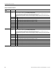
Word 4 Bits 00…15
(00…17)
Channel 1 Gate interval – Sets the individual counter gate interval using the time base setting as its time unit.
Actual gate interval is time base X gate interval (for instance, time base of 10 X gate interval of 5 = 50 ms). Maximum
value is 3 s.
Gate interval must be entered when PWM and rate measurement are configured.
Word 5 Bits 00…15
(00…17)
Do not use – reserved.
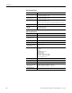
Word 6 and 7 Bits 00…15
(00…17)
Channel 0 Rollover – Sets the number of counts the counter accumulates before rolling over. For example, a setting
of 1000 produces a count sequence of 998, 999, 0, 1, 2... while incrementing; and 2, 1, 0, 999, 998... while
decrementing. Rollover is a 32-bit number with a usable range of 16,777,216. In PWM, this value is zero; in count, X1
encoder, X2 encoder and X4 encoder configurations, it must be some specified nonzero number. The value doesn.t
matter in period/rate, continuous/rate and rate measurement configurations.
Word 8 and 9 Bits 00…15
(00…17)
Channel 1 Rollover – Sets the number of counts the counter accumulates before rolling over. For example, a setting
of 1000 produces a count sequence of 998, 999, 0, 1, 2... while incrementing; and 2, 1, 0, 999, 998... while
decrementing. Rollover is a 32-bit number with a usable range of 16,777,216. In PWM, this value is zero; in count, X1
encoder, X2 encoder and X4 encoder configurations, it must be some specified nonzero number. The value doesn.t
matter in period/rate, continuous/rate and rate measurement configurations.
Word 10 and 11 Bits 00…15
(00…17)
Channel 0 Preset – This word sets the preset value the counter is loaded with when CP is asserted. This number has
a range of 0 ≤ value ≤ 16,777,216.
Word 12 and 13 Bits 00…15
(00…17)
Channel 1 Preset – This word sets the preset value the counter is loaded with when CP is asserted. This number has
a range of 0 ≤
value ≤ 16,777,216.
Configuration Word Definition
Configuration
Word
Bit Definition