
User Manual User Manual

42 Rockwell Automation Publication 1794-UM010D-EN-E - July 2013
Communicate With Your Module
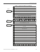
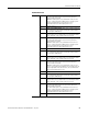
Word 2 00…15
(00…17)
Channel 0 PWM Output value – When the module is configured for
PWM, the time base is enabled, the counter for the respective channel,
its gate interval, rollover and 1st on and 1st off value are used. Ties can
be used to direct the PWM signal to any or all outputs.
The range of the PWM values is 0 ≤ value ≤ 9500 decimal (for instance,
0.00% ≤ value ≤ 95.00%). The actual duty cycle at the output depends
on the turn on and turn off times of the MOSFET, energy storage
capability of the cable/load and the resistance from output to return.
Word 3 00…15
(00…17)
Channel 1 PWM Output value – When the module is configured for
PWM, the time base is enabled, the counter for the respective channel,
its gate interval, rollover and 1st on and 1st off value are used. Ties can
be used to direct the PWM signal to any or all outputs.
The range of the PWM values is 0 ≤ value ≤ 9500 decimal (for instance,
0.00% ≤ value ≤ 95.00%). The actual duty cycle at the output depends
on the turn on and turn off times of the MOSFET, energy storage
capability of the cable/load and the resistance from output to return.
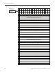
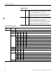
Bit/Word Definitions
Configuration Word Definition
Configuration
Word
Bit Definition
Configuration
Word 0
Counter Configuration – The upper byte of this word configures counter 1, the lower byte configures counter 0.
Bits 00…03 03 02 01 00 Counter 0
Bits 08…11
(10…13)
11
(13)
10
(12)
09
(11)
08
(10)
Counter 1
0 0 0 0 Counter
000 1Encoder
001 0Encoder X2
001 1PWM
010 0Encoder X4
0 1 0 1 Period/Rate
0 1 1 0 Continuous/Rate
0 1 1 1 Rate Measurement
Mode Selection
Bits 04…07 06 05 04 Counter 0
Bits 12…14
(14…16)
14
(16)
13
(15)
12
(14)
Counter 1
0 0 0 Store count disabled
0 0 1 Mode 1 – store/continue
0 1 0 Mode 2 – store/wait/resume
0 1 1 Mode 3 – store;reset/wait/start
1 0 0 Mdoe 4 – store;reset/start
Bit 15 (17) Invert the Z signal – 0 = Z not inverted; 1 = Z inverted