
User Manual User Manual

40 Rockwell Automation Publication 1794-UM010D-EN-E - July 2013
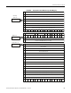
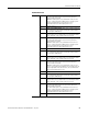
Communicate With Your Module
Bit/Word Definitions
Output
Word
Bit Definition
Word 0 00…15
(00…17)
Counter Control Word
00 Channel 0 Counter reset bit (CR) – A 0 to 1 transition of this bit
clears the counter. Outputs are adjusted according to the window
compare values.
01 Channel 0 Counter preset bit (CP) – A 0 to 1 transition of this bit sets
the counter to the value specified by the preset words. Outputs are
adjusted according to the window compare values.
02 Channel 0 Value reset bit (VR) – A 0 to 1 transition of this bit clears
the stored/accumulated count words.
03 This bit is always 0.
04 Channel 1 Counter reset bit (CR) – A 0 to 1 transition of this bit
clears the counter. Outputs are adjusted according to the window
compare values.
05 Channel 1 Counter preset bit (CP) – A 0 to 1 transition of this bit sets
the counter to the value specified by the preset words. Outputs are
adjusted according to the window compare values.
06 Channel 1 Value reset bit (VR) – A 0 to 1 transition of this bit clears
the stored/accumulated count words.
07 This bit is always 0.
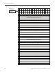
08…10
(10…12)
Reserved for factory use.
11 (13) Frequency/Resolution enhancement bit (M11) Set this bit to 1 for
frequency precision configuration (Refer to Word 8 Bit/Word Definitions
on page 39 for details on frequency precision configuration).
Note: You must place a value between -4 and +2 in output word 2 and/
or 3 to shift the decimal position accordingly.
12…15
(14…17)
Reserved for factory use.
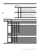
Word 1 00…15
(00…17)
Output Control Word
00 Output 0 Force output bit (FO) – When set to 1, output is turned on if
OE is 1. When FO = 0, output can be controlled by a compare match or
as directed by the PWM settings.
01 Output 0 Output enable bit (OE) – When set to 1, output can be
turned on from a force on, compare match or as directed by the PWM
settings. When OE = 0, the associated output is turned off.