
User Manual User Manual

26 Rockwell Automation Publication 1794-UM010D-EN-E - July 2013
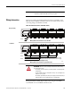
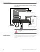
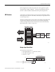
Install Your FLEX I/O VHSC Module
Connections for Terminal Base 1794-TB3G or 1794-TB3GK shown
17 18 19 20 21 22 23 24 25 26 27 28 29 30 31 32
0 1 2 3 4 5 6 7 8 9 10 11 12 13 14 15
16
35 36 37 38 39 40 41 42 43 44 45 46 47 48 49 50 51
34
COM
6 Chassis ground
for shields
Chassis GND
Chassis GND
AAB
BZ
O1O0 O3O2
O1O0
O3
O2
Z
A
AB
BZ
ZAAB
BZ
Z
AAB
BZ
Z
24V inputs
24V inputs
5V inputs
5V inputs
-V+V-V+V
+24V
COM
+24V
24V DC
base power
24V DC
base power
A, A - incremental encoder input A (+5 or +24V DC)
B B
- incremental encoder input B (+5 or +24V DC)
Z, Z - incremental encoder input Z (+5 or +24V DC)
O = sourcing outputs
R = returns for sourcing outputs
+V = +5 or +24V DC isolated power externally supplied for outputs (1 A max)
-V = negative isolated power connection (1 A max)
+24V DC = 24V DC terminal base power for module
COM = return for +24V DC terminal base power for module
Chassis Gnd = chassis ground for input or output cable shields
45898
Where:
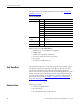
Wiring connections for the 1794-VHSC High Speed Counter Module
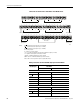
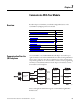
Incremental
Encoder Input
Terminal Base Units 1794-TB3G, 1794-TB3GK,
1794-TB3GS
Channel 0 Channel 1
+24V Inputs
Input A 0 8
Input A
19
Input B 2 10
Input B
311
Input Z 4 12
Input Z
513
+5V Inputs
Channel 0 Channel 1
Input A 17 25
Input A
18 26
Input B 19 27