
User Manual User Manual

24 Rockwell Automation Publication 1794-UM010D-EN-E - July 2013
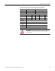
Install Your FLEX I/O VHSC Module
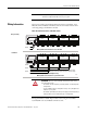
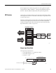
1794-TB3G, 1794-TB3GK and 1794-TB3GS Wiring Connections
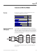
Connect Wiring to the FLEX I/O VHSC Input Module
Wiring to the 1794-VHSC Input module is made through the terminal base unit
on which the module mounts.
The module is compatible with the 1794-TB3G, 1794-TB3GK and 1794-
TB3GS terminal base units.
Connect Wiring Using a 1794-TB3G, 1794-TB3GK or 1794-TB3GS
Terminal Base Unit
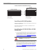
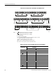
1. Connect the individual signal wiring to numbered terminals on the 0…15
row (A) for 24V inputs (terminals 0…5 and 8…13) and 17…32 row (B) for
5V inputs (terminals 17…22 and 25…30) on the terminal base unit.
Connect the input devices as shown in Ta b l e
Wiring connections for the
1794-VHSC High Speed Counter Module on page 26.
2. Connect individual output wiring to terminals 6, 7 and 14, 15 on the
0…15 row (A) and terminals 23, 24 and 31, 32 on the 16…32 row (B) on
the terminal base unit. Connect output return wiring for channels 0, 1, 2,
and 3 to terminals 23, 24 31 and 32 respectively. Connect the output
devices as shown in Tabl e
Wiring connections for the 1794-VHSC High
Speed Counter Module on page 26
3. Terminate shields to terminals 16 or 33 on row B, or 40…45 on row C.
0123456789101112131415
16 17 18 19 20 21 22 23 24 25 26 27 28 29 30 31 32 33
34 35 36 37 38 39 40 41 42 43 44 45 46 47 48 49 50 51
A
B
C
A
B
C
1794-TB3G or 1794-TB3GK
1794-TB3GS
0...15
34...51
16...33
0 1 2 3 4 5 6 7 8 9 10 11 12 13 14 15
18 19 20 21 22 23 3324 25 26 27 28 29 30 31 3217
35 36 37 38 47 48 49 5034 51
16
39 40 41 42 43 44 45 46
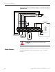
Label placed at top of wiring area
34 and 50 = 24V DC
35 and 51 = common
16 and 33 = chassis
40…45 = chassis ground
35 and 51 = common
34 and 50 = 24V DC
16 and 33 = chassis ground
40…45 = chassis ground
45328
ATTENTION: Do not connect 24V signals to the 5V input terminals.
Permanent damage to the module will result.