
User Manual User Manual

Rockwell Automation Publication 1794-UM010D-EN-E - July 2013 9
Overview of the Very High Speed Counter Module
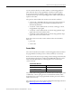
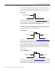
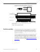
Period/Rate Mode
In Figure Period/Rate Mode on page 9, the incoming pulse train from the gate/
reset terminal is used to sample pulses from the 5 MHz internal clock. As the
frequency of the incoming pulse train at the gate/reset terminal increases, the
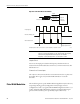
number of sampled pulses from the 5 MHz clock decreases. This relationship is
shown in NO TAG. Since accuracy is related to the number of pulses received
over the sample period, the accuracy will decrease with increasing input
frequencies at the Gate/Reset terminal.
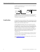
To some extent, the decrease in accuracy can be lessened by scaling the input
frequency through the use of a scaler. A scaler value of 1 will only return an
accurate input frequency if incoming pulses have a 50% duty cycle.
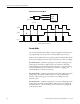
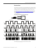
Incoming pulse train at Z
(gate/reset terminal)
5 MHz internal clock
A (not used)
B (not used)
Input A
Input B
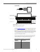
Single phase pulse generator
1794-VHSC
Input Z
scaler
5 MHz clock
1
Accumulated count
Frequency and outputs
updated here
10 20
Z (gate/reset)
Assumes symmetrical pulse, 50% duty cycle, so period = sample time on X 2 (on and off)
Frequency = 1/period
If count = 25, scaler = 1, and clock period = (1/5 MHz)
Frequency = 1 / [(25/1) X (1/5 MHz) X 2] = 100 KHz
45893
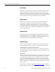
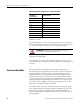
Relationship Between Sampled Pulses and Input Frequency
Input Frequency at Z
(Gate/Reset)
Terminal in Hz
Sampled Pulses for 1/2 Cycle of Z
(Gate/Reset) Pulse
21.25M
5500K
10 250K
20 125K
50 50K
100 25K