User Manual 1794 FLEX I/O Very High Speed Counter Module Catalog Numbers 1794-VHSC
Important User Information Solid-state equipment has operational characteristics differing from those of electromechanical equipment. Safety Guidelines for the Application, Installation and Maintenance of Solid State Controls (publication SGI-1.1 available from your local Rockwell Automation sales office or online at http://www.rockwellautomation.com/literature/) describes some important differences between solid-state equipment and hard-wired electromechanical devices.
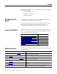
Summary of Changes This manual contains new and updated information. Changes throughout this revision are marked by change bars, as shown to the right of this paragraph. New and Updated Information This table contains the major changes and additions made to this revision. Topic Page Updated Frequency Resolution/Enhancement section. 33 Updated Word 8 Bit/Word Definitions.
Summary of Changes Notes: iv Rockwell Automation Publication 1794-UM010D-EN-E - July 2013
Preface Read this preface to familiarize yourself with the rest of the manual. It provides information concerning: • who should use this manual • the purpose of this manual • related documentation Who Should Use this Manual You must be able to program and operate an Allen-Bradley programmable controller (PLC) to make efficient use of this module. We assume that you know how to do this in this manual.
Preface Resource Description Industrial Automation Wiring and Grounding Guidelines, publication 1770-IN041 Provides general guidelines for installing a Rockwell Automation industrial system. Product Certifications website, http://ab.com Provides declarations of conformity, certificates, and other certification details. Application Considerations for Solid-State Controls, publication SGI-1.
Table of Contents Summary of Changes New and Updated Information. . . . . . . . . . . . . . . . . . . . . . . . . . . . . . . . . . . . . iii Preface Who Should Use this Manual . . . . . . . . . . . . . . . . . . . . . . . . . . . . . . . . . . . . . . . v Purpose of this Manual . . . . . . . . . . . . . . . . . . . . . . . . . . . . . . . . . . . . . . . . . . . . . v Additional Resources . . . . . . . . . . . . . . . . . . . . . . . . . . . . . . . . . . . . . . . . . . . . . . .
Mount the 1794-VHSC Module on the Terminal Base Unit . . . . . 21 Wiring Information . . . . . . . . . . . . . . . . . . . . . . . . . . . . . . . . . . . . . . . . . . . . . . 23 Connect Wiring to the FLEX I/O VHSC Input Module . . . . . . . . 24 Connect Wiring Using a 1794-TB3G, 1794-TB3GK or 1794-TB3GS Terminal Base Unit . . . . . . . . . . . . . . . . . . . . . . . . . . . . . . . . . . . . . . . . . . . 24 Chapter Summary . . . . . . . . . . . . . . . . . . . . . . . . . . . . . . . . . . . . . . . . .
Chapter 1 Overview of the Very High Speed Counter Module Overview Module Description This chapter gives you information on features of the modules, how the module communicates with controllers and how the module operates. Topic Page Module Description 1 Encoder or Counter Mode 2 Period/Rate Mode 8 Continuous/Rate Mode 10 Rate Measurement Mode 11 Pulse Width Modulation 12 Outputs 13 What the Module Does 14 The 1794-VHSC module performs high speed counting for industrial applications.
Overview of the Very High Speed Counter Module The module features include: • 2 counters configurable for 3 encoder modes, counter mode, period/rate mode, continuous/rate mode, rate measurement and pulse width modulation (PWM) • 4 outputs, isolated in pairs • outputs are current-sourcing at 5 or 12…24V DC (0.
Overview of the Very High Speed Counter Module Use the encoder modes if you need the module to read incoming quadrature pulses and return them to the programmable controller as a binary number (0…16,777,215). In these modes, the module accepts two-phase quadrature feedback and counts up or down depending upon the condition of the phase B input for each counter. The operation of the module in the encoder/counter modes is as follows: • counter mode – channel B is direction control (up or down).
Overview of the Very High Speed Counter Module Block Diagram of Counter Mode A Input A B Single phase pulse generator Input B Z (Store count) (Gate/Reset) Input Z 1794-VHSC Count up Count down A input + B input - Count 0 1 2 3 2 Outputs updated continuously 1 0 45891 Encoder Mode The encoder mode allows the module to read incoming pulses and return them to the programmable controller processor as a binary number (0-16,777,215).
Overview of the Very High Speed Counter Module Direction of Count The module can count either up or down, depending upon the condition of the B input for each counter. In encoder applications, the counter will increment on the leading edge of input A, while input B determines the direction of the count. You also have the option of X1, X2 and X4 multiplying of the input pulses.
Overview of the Very High Speed Counter Module Preset Value Each of the 2 counters has one preset value associated with it. In the encoder or counter modes, the preset value represents a reference point (or count) from which the module begins counting. The module can count either up or down from the preset value. Preset values are loaded into the count registers through the preset count bits. Preset values can range from 0 to 16,777,215 binary.
Overview of the Very High Speed Counter Module the counter to be read and stored. The counter will continue counting. The stored count will be available in the Read Data file. The stored count information will remain in the block transfer read file until it is overwritten by new data. Store/Continue Read, Store Count and continue counting.
Overview of the Very High Speed Counter Module is available in the Read Data file. The stored count remains in the Read Data file until it is overwritten with new data. Store-Reset/Start Falling edge Rising edge Store Count, reset to zero, start counting Store Count, reset to zero, start counting The figures show the store count feature operating on the rising edge of the gate/ reset pulse. The user has the option of electing these same features using the falling edge of the gate/reset pulse.
Overview of the Very High Speed Counter Module Period/Rate Mode A (not used) B (not used) Input A Input B Z (gate/reset) Input Z scaler 5 MHz clock 1794-VHSC Single phase pulse generator Incoming pulse train at Z (gate/reset terminal) 5 MHz internal clock 1 10 20 Frequency and outputs updated here Accumulated count Assumes symmetrical pulse, 50% duty cycle, so period = sample time on X 2 (on and off) Frequency = 1/period If count = 25, scaler = 1, and clock period = (1/5 MHz) Frequency = 1 / [(25
Overview of the Very High Speed Counter Module Relationship Between Sampled Pulses and Input Frequency Input Frequency at Z (Gate/Reset) Terminal in Hz Sampled Pulses for 1/2 Cycle of Z (Gate/Reset) Pulse 200 12.5K 500 5K 1 KHz 2.5K 2 KHz 1.25k 5 KHz 500 10 KHz 250 20 KHz 125 50 KHz 50 100 KHz 25 Operation of Scaler In period/rate mode, the scaler lets the incoming pulse train at the Z (gate/reset) terminal be divided by a user defined number.
Overview of the Very High Speed Counter Module Period/Rate and Continuous/Rate Output Operation with Scaler of 1 A (not used) B (not used) Z (Gate/Reset) Encoder/Pulse generator Input A Input B Input Z scaler 5 MHz clock 1794-VHSC Incoming pulse train at Z (gate/reset terminal) 5 MHz internal clock 1 10 20 Frequency updated here Accumulated count Outputs updated continuously 45894 Assumes symmetrical pulse, 50% duty cycle, so period = sample time on X 2 (on and off) Frequency = 1/period If count =
Overview of the Very High Speed Counter Module Operation of the Rate Measurement Mode A Input Input A B (not used) Input B Z (not used) Encoder/Pulse generator (Gate/Reset) Input Z Time base 1794-VHSC A Input (pulse) Internal sampling gate 1 2 3 Accumulated count Frequency calculated, outputs updated here If sample period is 50 ms, and count = 3, then frequency = 3/50 ms = 60 Hz EXAMPLE 45895 In , three counts have been accumulated during the user-selected time period.
Overview of the Very High Speed Counter Module Outputs The 1794-VHSC module has 4 outputs, isolated in groups of 2. Each of the outputs is capable of sourcing current and will operate between 5 and 24V DC. You must connect an external power supply to each of the outputs. The outputs can source 1 A DC alone or in combination. The outputs are hardware-driven and will turn on in about 25 s when the appropriate count value has been reached.
Overview of the Very High Speed Counter Module Effect of Values in On/Off Operation Output remains energized for 3000 additional counts Output turns on at count value of 2000 Output turns off at count value of 5000 Output turns off at count value of 2000 When values in Counter On Value are less than values in Counter Off Value. Output turns on at count value of 5000 When values in Counter On Value are greater than values in Counter Off Value.
Overview of the Very High Speed Counter Module FLEX I/O Communication Process 1 2 The adapter transfers your configuration data to the module. External devices transmit frequency signals to the module. FlexBus Allen-Bradley 4 VERY HIGH SPEED COUNTER MODULE 1794-VHSC The adapter transfers the data over the FlexBus. 1 ok 5 3 The adapter and module determine that the transfer was made without error and input values are within a specified range.
Overview of the Very High Speed Counter Module Notes: 16 Rockwell Automation Publication 1794-UM010D-EN-E - July 2013
Chapter 2 Install Your FLEX I/O VHSC Module Overview This chapter describes how to physically install the 1794-VHSC adapter on the DIN rail and connect it to the EtherNet/IP network.
Install Your FLEX I/O VHSC Module Install the Module Installation of the module consists of: • mount the terminal base unit • install the 1794-VHSC module into the terminal base unit • install the connecting wiring into the terminal base unit If you are installing your module into a terminal base unit that is already installed, proceed to See Mount on a DIN Rail on page 18. Mount on a DIN Rail ATTENTION: Do not remove or replace a terminal base unit when power is applied.
Install Your FLEX I/O VHSC Module 3. Position the terminal base at a slight angle and hooked over the top of the 35 x 7.5 mm DIN rail A (Allen Bradley part number 199-DR1; 46277-3). 22 ++ 45320 4. Slide the terminal base over tight against the adapter, or proceeding terminal base. Make sure the hook on the terminal base slides under the edge of the adapter, or proceeding terminal base, and the FlexBus connector is fully retracted. 5.
Install Your FLEX I/O VHSC Module For specific wiring information, refer to the installation instructions for the module you are installing in this terminal base unit. 7. Repeat the above steps to install the next terminal base unit. Ensure that the cover of the FlexBus connector on the last terminal base unit is in place. Mount on a Panel or Wall Installation of a FLEX I/O system on a wall or panel consists of: • laying out the drilling points on the wall or panel.
Install Your FLEX I/O VHSC Module Drilling Dimensions for Panel or Wall Mounting Millimeters (Inches) 35.5 (1.4) 58.5 (2.3) 35.5 (1.4) 58.5 (2.3) 35.5 (1.4) 21 (0.83) 45327 8. Drill the necessary holes for the #6 self-tapping mounting screws. 9. Mount the mounting plate for the adapter module using two #6 selftapping screws – 18 screws are included for mounting up to 8 modules and the adapter. IMPORTANT Make certain that the mounting plate is properly grounded to the panel.
Install Your FLEX I/O VHSC Module FLEX I/O Terminal Base and Very High Speed Counter Parts 2 3 1 4 5 6 8 7 40231 Label here or under here Description Description 1 FlexBus connector 5 Base unit 2 Latching mechanism 6 Alignment groove 3 Keyswitch 7 Alignment bar 4 Cap plug 8 Module 2. Make certain the FlexBus connector (1) is pushed all the way to the left to connect with the neighboring terminal base or adapter. You cannot install the module unless the connector is fully extended. 3.
Install Your FLEX I/O VHSC Module IMPORTANT Wiring Information The adapter is capable of addressing eight modules. Do not exceed a maximum of eight terminal base units in your system. This section provides essential wiring information for the 1794-TB3G, 1794TB3GK, and 1794-TB3GS terminal base units. It also includes instructions for connecting wiring to the FLEX I/O module.
Install Your FLEX I/O VHSC Module 1794-TB3G, 1794-TB3GK and 1794-TB3GS Wiring Connections 1794-TB3GS 0 1 2 3 4 5 6 7 8 9 10 11 12 13 14 15 16 17 18 19 20 21 22 23 24 25 26 27 28 29 30 31 32 33 34 35 36 37 38 39 40 41 42 43 44 45 46 47 48 49 50 51 1794-TB3G or 1794-TB3GK 0 1 2 3 4 5 6 7 8 Label placed at top of wiring area 9 10 11 12 13 14 15 A 0...15 A B 16...33 B C 34...
Install Your FLEX I/O VHSC Module 4. Connect 24V DC to terminal 34 on the 34…51 row (C), and 24V common to terminal 35 on the 34…51 row (C). ATTENTION: To reduce susceptibility to noise, power frequency modules and digital modules from separate power supplies. Do not exceed a length of 10 m (33 ft) for DC power cabling. 5.
Install Your FLEX I/O VHSC Module Connections for Terminal Base 1794-TB3G or 1794-TB3GK shown 0 1 2 3 4 5 6 7 8 A A B B Z Z O0 O1 A 9 10 A B B Z 13 14 15 Z O2 O3 17 18 19 20 21 22 23 24 25 26 27 28 29 30 A A B B Z Z O0 O1 A A B B Z Z 34 35 +24V COM 36 37 +V 31 32 O2 O3 5V inputs 5V inputs Chassis GND 38 39 40 41 42 43 44 45 6 Chassis ground for shields -V 24V DC base power Where: 12 24V inputs 24V inputs 16 11 Chassis GN
Install Your FLEX I/O VHSC Module Wiring connections for the 1794-VHSC High Speed Counter Module Input B 20 28 Input Z 21 29 Input Z 22 30 Outputs Output Sourcing Out Return Output Sourcing Out Return O0 6 23 O1 7 24 O2 14 31 O3 15 32 +24V DC Base power Terminals 34 and 50 +24V DC COM Terminals 35 and 51 +5V or +24V Output power Terminals 37 and 46 -V Output power Terminals 39 and 48 Chassis GND Terminals 16, 33, and 40…45 ATTENTION: Total current draw through the termi
Install Your FLEX I/O VHSC Module Example of Quadrature Encoder Differential Wiring to a 1794-TB3G or 1794-TB3GK Terminal Base Unit A B Z (Store count) (Gate/reset) Quadrature encoder (for example: 845H-SJ__24DRY__ ) Mechanical switch 0 0 16 1 1 17 34 2 18 35 3 2 3 19 36 4 4 20 37 5 5 21 38 6 6 22 39 7 23 40 8 7 8 24 41 9 9 25 42 10 10 26 43 11 11 27 44 12 12 28 45 13 14 15 13 29 46 14 30 47 15 31 48 32 49 33 50 51 0…15 A 16…33 B 34…51 C 1794-TB3G 24V Base pow
Chapter 3 Communicate With Your Module Overview Read this chapter to familiarize yourself with configurable features on the 1794-VHSC Very High Speed Counter module Communication Over the I/O Backplane For Information About See Page Communication Over the I/O Backplane 29 I/O Structure 31 Safe State Data 32 Device Actions 32 1794-VHSC — High Speed Counter Module Image Table Mapping 35 Input Status Word Bits 32 Bit/Word Definitions 37 Configuration Word Definition 42 One 1794-AENT or
Communicate With Your Module Scheduled Data-Transfer Scheduled data transfer: • is continuous • is asynchronous to the ladder-logic program scan • occurs at the actual rate displayed in the Actual Packet Interval field on the programming software I/O mapping (monitor) screen Unscheduled Data-Transfer Unscheduled operations include: • unscheduled non-discrete I/O data transfers — through I/O transfer instructions • peer-to-peer messaging — through Message (MSG) instructions • messaging from programming dev
Communicate With Your Module If the configuration is considered acceptable, the counter application specific integrated circuit (ASIC) is disabled — counting is suspended and outputs are shut off — while the ASIC is loaded with the new operational parameters. I/O Structure Output data is received by the adapter in the order of the installed I/O modules. The Output data for Slot 0 is received first, followed by the Output data for Slot 1, and so on up to slot 7.
Communicate With Your Module The adapter input status word bit descriptions are show in Table Input Status Word Bits on page 32. Input Status Word Bits Bit Description Bit Explanation I/O Module Fault 0 This bit is set (1) when an error is detected in slot position 0. 1 This bit is set (1) when an error is detected in slot position 1. 2 This bit is set (1) when an error is detected in slot position 2. 3 This bit is set (1) when an error is detected in slot position 3.
Communicate With Your Module Communication Fault Behavior You can configure the 1794-VHSC response to a communication fault. Upon detection of a communication fault, the module can: • leave the module output data in its last state (hold last state) • reset the module output data to zero (reset) • apply safe state data to the module output Idle State Behavior The 1794-VHSC module responds to idle state according to the Communication Fault Behavior described above.
Communicate With Your Module moves decimal point left 2 places dividing the frequency value by 100; +1 moves the decimal point 1 place, multiplying by 10, and so on. This allows frequency values to fit in a single word. Applying the Frequency/Resolution Enhancement To use this mode, proceed as follows. ATTENTION: Use this enhancement mode with caution since no checks are performed to verify data. Unintended operation can occur. 1. Power up the FLEX chassis, or put the controller into RUN mode, or both.
Communicate With Your Module 1794-VHSC — High Speed Counter Module Image Table Mapping I/O Image 0 Channel 0 Current Count (least significant word) 1 Channel 0 Current Count (most significant word) 2 Channel 1 Current Count (least significant word) 3 Channel 1 Current Count (most significant word) 4 Channel 0 Stored/Accumulated Count (least significant word) 5 Channel 0 Stored/Accumulated Count (most significant word) 6 Channel 1 Stored/Accumulated Count (least significant word) 7 Channel
Communicate With Your Module Configuration Size (continued) 56 Words 17 0 0 0 0 0 0 0 0 S4 S3 S2 S1 F4 F3 F2 F1 18 0 0 0 0 0 0 0 0 S4 S3 S2 S1 F4 F3 F2 F1 19 0 0 0 0 0 0 0 0 S4 S3 S2 S1 F4 F3 F2 F1 20 First Counter 1st On Value (least significant word) 21 First Counter 1st On Value (most significant word) 22 First Counter 1st Off Value (least significant word) 23 First Counter 1st Off Value (most significant word) 24 First Counter 2nd On Value (l
Communicate With Your Module Bit/Word Definitions Input Word Bit Definition Word 0 00…15 (00…17) Word 1 00…15 (00…17) Channel 0 current count – The current count consists of 2 words (32 bits) representing the current count of the 24-bit counter (in encoder, X2 encoder, X4 encoder, PWM) or the frequency (in periodrate, continuousrate, rate measurement.). The range of values is (0 < value < 16,777,215).
Communicate With Your Module Bit/Word Definitions Input Word Bit Word 8 38 Definition Module Channel Status Word 00 Zero input status bit (ZS) for Channel 0 – This bit represents the present status of the Z input. 0 = Off 1 = Input on This bit is uneffected by Z invert, ZI, in the counter configuration word. 01 Zero frequency detected bit (ZF) for Channel 0 – Only used during frequency configurations (period/rate, continuous/rate, and rate measurement).
Communicate With Your Module Bit/Word Definitions Input Word Bit Definition Word 8 12 (14) Test/fail bit (TF) – If the flexbus power or terminal base power is applied and the module fails during hardware tests, a fatal error occurs. The TF bit is asserted and the red module indicator turns on. An error code will be set in the module/channel status word which can be read using an instruction. The TF bit is also asserted if the upper byte of the counter control word is not zero.
Communicate With Your Module Bit/Word Definitions Output Word Bit Definition Word 0 00…15 (00…17) Counter Control Word 00 Channel 0 Counter reset bit (CR) – A 0 to 1 transition of this bit clears the counter. Outputs are adjusted according to the window compare values. 01 Channel 0 Counter preset bit (CP) – A 0 to 1 transition of this bit sets the counter to the value specified by the preset words. Outputs are adjusted according to the window compare values.
Communicate With Your Module Bit/Word Definitions Rockwell Automation Publication 1794-UM010D-EN-E - July 2013 02 Output 0 Local control bit (LC) – When set to 1, output is controlled the counter if the FlexBus power is lost (for instance, the module detects a FlexBus reset signal). Note: When FlexBus power is lost, communication to the PC is lost. When LC = 0, the module clears its OE bit at a loss of FlexBus power.
Communicate With Your Module Bit/Word Definitions Word 2 00…15 (00…17) Channel 0 PWM Output value – When the module is configured for PWM, the time base is enabled, the counter for the respective channel, its gate interval, rollover and 1st on and 1st off value are used. Ties can be used to direct the PWM signal to any or all outputs. The range of the PWM values is 0 ≤ value ≤ 9500 decimal (for instance, 0.00% ≤ value ≤ 95.00%).
Communicate With Your Module Configuration Word Definition Configuration Word Bit Word 1 Definition Filter Selection – Only 1 filter selection can be chosen at a time. Frequency = 50% duty cycle. Bits 00…03 03 02 01 00 Counter 0 Bits 08…11 (10…13) 11 (13) 10 (12) 09 (11) 08 (10) Counter 1 0 0 0 0 No filter 0 0 0 1 50 kHz (10 μs + 0 μs/-1.6 μs) 0 0 1 0 5 kHz (100 μs + 0 μs/-13.2 μs) 0 1 0 0 500 Hz (1.0 ms + 0 ms/-1.25 μs) 1 0 0 0 50 Hz (10.0 ms + 0 ms/-1.
Communicate With Your Module Configuration Word Definition Configuration Word Bit Definition Word 14 Bits 00…15 (00…17) Channel 0 Scaler – This word scales the Z signal in period/rate and continuous/rate modes. If the filter is applied, the filtered Z signal is scaled. Set only 1 bit of the Scaler. Selecting a Scaler causes accumulated counts to be adjusted accordingly (for instance, selecting a Scaler of 128 increases the accumulated count by 128 after 128 Z pulses have been received).
Communicate With Your Module Configuration Word Definition Configuration Word Bit Definition Words 16…19 Bits 00 01 02 03 04 05 06 07 Bits 08…15 (10…17) Output Ties – These bits connect the specified output to the appropriate compare window. There are 8 windows, 4 per counter. Each output can be connected to any number of windows, from 1 to 8.
Communicate With Your Module 46 Rockwell Automation Publication 1794-UM010D-EN-E - July 2013
Chapter 4 Interpret Status Indicators for your FLEX I/O Module Overview Use this chapter to troubleshoot the very high speed counter module by interpreting the indicators.
Interpret Status Indicators for your FLEX I/O Module Use the following table to determine the indicator conditions and status. Status Indicator Identification Indicator State Status A (status of input A) Yellow Input A active. Off Input A not active. Yellow Input B active. Off Input B not active. Yellow Input Z active. Off Input Z not active. Yellow Output is on. Off Individual output is off.
Interpret Status Indicators for your FLEX I/O Module Diagnostic Codes Returned by the Module If an incomplete, incorrect or conflicting set of configuration parameters are sent to the module, the PE bit is asserted, the green module status indicator flashes, and an error code is displayed in bits 0…11 of the module/channel status word. These codes are identified below. Diagnostics Reported by Input Data Word 8 Read Word Word 8 Bit 00 01 Indication A reserved configuration or mode was programmed.
Interpret Status Indicators for your FLEX I/O Module Notes: 50 Rockwell Automation Publication 1794-UM010D-EN-E - July 2013
Appendix A Specifications Overview This appendix contains general and environmental specifications and certifications for the FLEX I/O Very High Speed Counter Module. Input Specifications Attribute Value Number of input channels 2 Number of inputs per counter 2 groups of A/A, B/B, and Z/Z pairs with 5V DC or 15…24V DC terminations Input voltage 5V DC or 15…24V DC (Determined by terminal base terminations) Input current 5V DC terminations: 19.1 mA @ 5V DC 25.
Specifications Output Specifications Attribute Value Current, on-state, max 5V DC terminations: 0.5 A 12…24V DC terminations: 1.0 A Current per output pair, max 5V DC terminations: 0.5 A 12…24V DC terminations: 1.0 A Short circuit current 5V DC terminations: 0.9A 12…24V DC terminations: 4.0A Outputs are short-circuit protected and turned off until power is cycled.
Specifications Environmental Specifications Attribute Value Temperature, operating IEC 60068-2-1 (Test Ad, Operating Cold), IEC 60068-2-2 (Test Bd, Operating Dry Heat), IEC 60068-2-14 (Test Nb, Operating Thermal Shock): 0…55 °C (32…131 °F) Temperature, nonoperating IEC 60068-2-1 (Test Ab, Un-packaged Non-operating Cold), IEC 60068-2-2 (Test Bb, Un-packaged Non-operating Dry Heat), IEC 60068-2-14 (Test Na, Un-packaged Non-operating Thermal Shock): -40…85 °C (-40…185 °F) Relative humidity IEC 60068-2-
Specifications Certifications Certification (when Description product is marked)(1) CE European Union 2004/108/EC EMC Directive, compliant with: EN 61326-1; Meas./Control/Lab.
Appendix B Programming Your Very High Speed Counter Module To initiate communication between the 1794-VHSC very high speed counter module and your PLC processor, you must use RSLogix 5000 software. Refer to the RSLogix software manuals for information on communicating with this 1794-VHSC very high speed counter module.
Programming Your Very High Speed Counter Module Notes: 54 Rockwell Automation Publication 1794-UM010D-EN-E - July 2013
Index Numerics 1794-TB3G 25, 27, 28, 29 1794-TB3GK 27, 28, 29 1794-TB3GS 25, 27, 28, 29 1794-VHSC 34, 49 description 5 features 5 interpret status indicator 49 A adapter 21, 23, 24, 25, 29 1794-VHSC 21 capabilities 27 install 21 maximum capacity 27 additional resources 3 B backplane 23, 26 behavior communication fault 36 idle state 36 input data 36 C cabling length 29 power 29 chassis 28, 29 codes diagnostic 51 error 51 compatible terminal base 28 configuration error 34 connect 28 connector 26 female 22
Index hazardous location 26 install connecting wiring 22 install module 21 mount terminal base 21 mounting kit 24 terminal base mounting 25 wall or panel mounting 24 K keyswitch 25 position 25 L location hazardous 26 M male connector 22 messaging from programming devices 34 peer-to-peer 34 mode continuous/rate 14 period/rate 14 rate measurement 15 module installation 21 position 29 specifications 53 mounting kit 24 N network EtherNet/IP 21 O operation unintended 22 output values 18 outputs connecting
Rockwell Automation Support Rockwell Automation provides technical information on the Web to assist you in using its products. At http://www.rockwellautomation.com/support/, you can find technical manuals, a knowledge base of FAQs, technical and application notes, sample code and links to software service packs, and a MySupport feature that you can customize to make the best use of these tools.