
Installation Instructions User guide


FLEX I/O Grounded Cage Clamp Temperature Terminal Base Unit 5
Publication 1794-IN133A-EN-P - May 2012
Environmental
Attribute Value
Temperature,
operating
IEC 60068-2-1 (Test Ad, Operating Cold),
IEC 60068-2-2 (Test Bd, Operating Dry Heat),
IEC 60068-2-14 (Test Nb, Operating Thermal Shock):
-20…70 °C (-4…158 °F)
Temperature,
surrounding air,
max
70 °C (158 °F)
Temperature,
nonoperating
IEC 60068-2-1 (Test Ab, Unpackaged Non-operating Cold),
IEC 60068-2-2 (Test Bb, Unpackaged Non-operating Dry
Heat),
IEC 60068-2-14 (Test Na, Unpackaged Non-operating
Thermal Shock):
-40…85 °C (-40…185 °F)
Relative humidity IEC 60068-2-30 (Test Db, Unpackaged Damp Heat):
5…95% noncondensing
Vibration IEC 60068-2-6 (Test Fc, Operating):
5 g @ 10…500 Hz
Shock, operating IEC 60068-2-27 (Test Ea, Unpackaged Shock):
30 g
Shock,
nonoperating
IEC 60068-2-27 (Test Ea, Unpackaged Shock):
50 g
Certifications
(1)
Attribute Value
c-UL-us UL Listed Industrial Control Equipment, certified for US and
Canada. See UL File E65584.
UL Listed for Class I, Division 2 Group A,B,C,D Hazardous Locations, certified for
U.S. and Canada. See UL File E194810.
CE
European Union 2004/108/EC EMC Directive, compliant with:
EN 61326-1; Meas./Control/Lab., Industrial Requirements
EN 61000-6-2; Industrial Immunity
EN 61000-6-4; Industrial Emissions
EN 61131-2; Programmable Controllers (Clause 8, Zone A & B)
C-Tick
Australian Radiocommunications Act, compliant with:
AS/NZS CISPR 11; Industrial Emissions
Ex
European Union 94/9/EC ATEX Directive, compliant with:
EN 60079-15; Potentially Explosive Atmospheres, Protection "n"
EN 60079-0; General Requirements
II 3 G Ex nA IIC T4 X
TÜV
TÜV Certified for Functional Safety:
Capable of SIL 2
(1)
See the Product Certification link at http://www.ab.com for Declaration of Conformity, Certificates, and
other certification details.
35
(1.4)
59
(2.3)
87
(3.4)
94
(3.7)
94
(3.7)
80
(3.2)
28
(1.2)
50
(2.0)
23
(0.9)
68
(2.7)
80
(3.2)
21 (0.83)
(3.4 x 2.7 x 2.7)
87 x 68 x 69
(3.7 x 3.7 x 2.7)
94 x 94 x 69
(3.7 x 3.7 x 2.7)
94 x 94 x 69
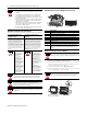
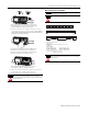
Secure DIN rail approximately every 200 mm (7.87 in.).
A = Mounting hole dimensions for optional mounting kit.
B = DIN rail.
C = Operating temperature 25.4 (1.0) below each module when mounted in any position
must not exceed 55 °C (131 °F).
Measure here for
vertical mounting
position with
adapter up.
Measure here for horizontal position.
A
B
C
Terminal Base (1794-TB3S shown) Terminal Base (1794-TB3GT shown)Adapter
94
(3.7)
94
(3.7)
35
(1.4)
Maintain at least 25.4 (1.0) air space around your FLEX I/O system installation.
Mounting Dimensions and Spacing Requirements
mm
(in.)