
Installation Instructions User guide


4 FLEX I/O Grounded Cage Clamp Temperature Terminal Base Unit
Publication 1794-IN133A-EN-P - May 2012
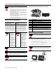
Typical Wiring Guidelines Specifications
ATTENTION
Total current draw through the terminal base unit is limited to 10 A.
Separate power connections may be necessary.
Wiring
when total current draw is less than 10 A
W
iring when total current draw is greater than 10 A
Daisy-chaining
Individual
Combination
24V
DC
24V DC
24V DC
24V DC
24V DC
24V DC
Note:
Use this configuration if using any
“noisy” DC digital I/O modules in your system.
Thermocouple
Module wiring separate from discrete wiring.
Note:
All modules powered by the same power supply
must be analog modules for this configuration.
Note:
All modules must be analog modules for this configuration.
Thermocouple
or
Analog Module
Thermocouple
or Analog Module
Thermocouple
or Analog Module
Thermocouple
or Analog Module
Thermocouple
or Analog Module
Thermocouple
or Analog Module
Thermocouple
or Analog Module
Thermocouple
or Analog Module
Thermocouple
or Analog Module
Thermocouple
or Analog Module
Thermocouple
or Analog Module
Thermocouple
or Analog Module
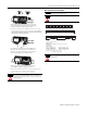
General
Attribute Value
Terminal screw
torque
0.79...1.02 Nm (7…9 lb-in.)
Current capacity,
max
V/COM terminals: 10 A
I/O terminals: 2 A
FlexBus current 5V DC, 640 mA
Voltage rating,
max
V/COM terminals: 31.2V DC/AC, 50/60 Hz
Isolation voltage 50V (continuous), Basic Insulation Type
Tested at 500V for 60 s, Field to FlexBus, or installed module.
Enclosure type
rating
None (open-style)
Wire size
0.21... 1.3 mm
2
(24…16 AWG) stranded copper wire rated at
75 °C (167 °F ) or greater, 1.2 mm (3/64 in.) insulation max
Wiring category
(1)
(1)
Use this Conductor Category information for planning conductor routing. Refer to Industrial Automation
Wiring and Grounding Guidelines, publication 1770-4.1.
Established by installed module
North American
temp code
T4A
IEC temp code T4
Dimensions,
approx.
(HxWxD)
94 x 94 x 69 mm
(3.7 x 3.7 x 2.7 in.)
(with module installed in terminal base)