
Install. Instr User guide


Publication 1794-IN069D-EN-P - June 2004 4 PN 957782-90
Supersedes Publication 1794-IN069C-EN-P - August 2002, and 1794-5.71 - May 2000 Copyright © 2004 Rockwell Automation, Inc. All rights reserved. Printed in the U.S.A.
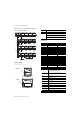
Derating Curve for 1794-PS3 (for any mounting other than
horizontal)
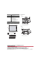
Mounting Dimensions
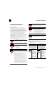
Conductors Wire Size
Category
1
22 to 12 AWG (0.34mm
2
- 2.5mm
2
) stranded copper wire rated at 75°C or
higher
3/64 inch (1.2mm) insulation maximum
2
Terminal Screw Torque 7 pound-inches (0.8Nm)
Certifications (when product is
marked)
2
CULUS UL Listed Industrial Control Equipment for Class I, Division
2, Groups A, B, C and D Hazardous locations
CULUS UL Listed Industrial Control Equipment, certified for US
and Canada
CE
2
European Union 89/336/EEC EMC Directive,
compliant with:
EN 61000-6-4; Industrial Emissions
EN 50082-2; Industrial Immunity
EN 61326; Meas./Control/Lab., Industrial Requirements
EN 61000-6-2; Industrial Immunity
European Union 73/23/EEC LVD Directive, compliant
with:
EN 61131-2; Programmable Controllers
C-Tick
2
- Australian Radiocommunications Act compliant with:
AS/NZS CISPR 11, Industrial Emissions
1 You use this category information for planning conductor routing as described in Allen-Bradley
publication 1770-4.1, Industrial Automation Wiring and Grounding Guidelines.
2 For the latest up-to-date information, see the Product Certification link at www.ab.com for Declarations of
Conformity, Certificates and other certification details. For notification of any additional release notes, refer to
www.ab.com/manuals/
0
0.5
0
2.0
1.0
3.0
10 20 30 40 50 55 60
Max.
Output
Current
(A)
Ambient Temperature
o
C
The area within the curve represents the safe operating range for the module under
various conditions of user supplied 24V dc supply voltages and ambient temperatures.
= Normal mounting safe operating range, (includes ).
= Other mounting positions (including inverted horizontal) safe operating range
2.8
2.5
1.5
Normal Mounting – Horizontal
Other Mounting (including Vertical, and Inverted Horizontal Mounting)
Inches
(Millimeters)
3.4
(87)
3.2
(80)
2.7
(68)
.83 (21)
1794-PS13
3.4H x 2.7W x 2.7D
(87H x 68W x 69D)
1.4
(35)
A
2.3
(59)
A
= Mounting hole dimensions for optional mounting kit
B
B
= DIN rail
2.0
(50)
1.2
(28)
C
C
= Secure DIN rail approximately every 200mm
Power
24V DC
POWER SUPPLY
1794-PS13
24V
COM
Inches
(Millimeters)
3.4
(87)
3.2
(80)
3.7
(94)
1794-PS3
3.4H x 3.7W x 2.7D
(87H x 95W x 69D)
A
B
= DIN rail
2.0
(50)
1.2
(28)
B = Secure DIN rail approximately every 200mm
Power
24V DC
POWER SUPPLY
1794-PS3
24V
COM
A
1794-PS13
1794-PS3