
User Manual
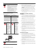
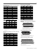
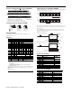
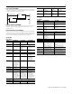
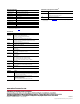
Table Of Contents
4
Publication 1794-IN124A-EN-P - January 2009
1794-TB3 and -TB3S Terminal Base Wiring for the 1794-IB10XOB6XT
2 and 3-Wire Input Wiring for 1794-IB16XT, -IB10XOB6XT
Configuring Your Module
You configure your output/input module by setting bits in the
configuration word.
Configuration
Setting the Input Filter Time (1794-IB16XT, -IB10XOB6XT)
To set the input filter time, set the associated bits in the output image table
(complementary word) for the module .
As an example for 1794-IB16XT, to increase the off-to-on filter time to 4 ms
for all inputs at address rack 1, module group 0, set bits and program as
shown below .
For 1794-IB10XOB6XT, increase the off-to-on filter time to 8 ms for all
inputs at address rack 1, module group 0, in configuration word 3, by
setting bits as shown below.
Refer to the Input Filter time chart below for other bit settings.
Input Filter Time (1794-IB16XT)
Input Filter Time (1794-IB10XOB6XT)
Dec. 15 14 13 12 11 10 9 8 7 6 5 4 3 2 1 0
Oct. 17 16 15 14 13 12 11 10 7 6 5 4 3 2 1 0
1794-OB8EPXT
Read F7 F6 F5 F4 F3 F2 F1 F0 Reserved (see note)
Write Not used FR O7 O6 O5 O4 O3 O2 O1 O0
Write
1794-OB16PXT
Read Not used
Write O15 O14 O13 O12 O11 O10 O9 O8 O7 O6 O5 O4 O3 O2 O1 O0
Write
1794-OB
32P only
O
31
O
30
O
29
O
28
O
27
O
26
O
25
O
24
O
23
O
22
O
21
O
20
O
19
O
18
O
17
O
16
1794-IB16XT
Read 1I15I14I13I12I11I10I9I8I7I6I5I4I3I2I1I0
Read 2 C = Counter Input value of input 15
Write 1 Not used CF CR Not used Input Filter
12-15
Input Filter
0-11
1794-IB10XOB6XT
Read 1 Not used I9 I8 I7 I6 I5 I4 I3 I2 I1 I0
Write 2 Not used O5 O4 O3 O2 O1 0O
Write 3 Not used FT Not used
Where: O = Output - O0 corresponds to output 0, O1 corresponds to output 1
F = Overload fault bits - 1 = fault present; 0 = no fault
FR = Fault reset bit - 1 = reset output; 0 = no change
I = Input
C = Counter value for input 15
CR = Counter reset
CF = Counter fast - where 1 = fast input (raw data), 0 = standard input filtered data
FT = Input Filter Time for input channels
1794-OB16PXT uses outputs 0-3
NOTE: C, CR and CF not available when used with any series 1794-ASB or 1794-ASB2 remote I/O
adapter modules.
NOTE: The unused lower byte in read word 1 floats during operation. Do not use this byte for fault
status.
See Programming below.
17 18 19 20 21 22 23 24 25 26 27 28 29 30 31 32 33
0 1 2 3 4 5 6 7 8 9 10 11 12 13 14 15
16
35 36 37 38 39 40 41 42 43 44 45 46 47 48 49 50 51
34
Inputs
Commons
(1794-TB3 shown)
-V (Supply Common) = Terminals B-16 and B-33
+V (Supply +Voltage In) = Terminals C-34 and C-51
-V
Voltage
In +V
Voltage
Out +V
Voltage
A
B
C
(Use B-33 and C-51 for daisy-chaining to next terminal base unit)
Common
-V
Common
Outputs
= Sink input
= Common
= +V dc
0-15
16-33
34-51
A
B
C
A
B
C
2-Wire Device
(Sourcing Output)
3-Wire Device
(Sourcing Output)
Bits Description - Filter Time Filter Time
02 01 00 Inputs 0 thru 11 1794-IB16XT
05 04 03 Inputs 12 thru 15
0 0 0 Filter time 0 (default) 0.25 ms
0 0 1 Filter time 1 0.5 ms
0 1 0 Filter time 2 1 ms
0 1 1 Filter time 3 2 ms
1 0 0 Filter time 4 4 ms
1 0 1 Filter time 5 8 ms
1 1 0 Filter time 6 16 ms
1 1 1 Filter time 7 32 ms
Bits Description
10 09 08 Filter Time for Inputs Off to On/On to Off
0 0 0 Filter Time 0 0.25 ms
0 0 1 Filter Time 1 0.5 ms
0 1 0 Filter Time 2 1.0 ms
0 1 1 Filter Time 3 2.0 ms
1 0 0 Filter Time 4 4.0 ms
1 0 1 Filter Time 5 8.0 ms
1 1 0 Filter Time 6 16.0 ms
1 1 1 Filter Time 7 32.0 ms
15 14 13 12 11 10 9 8 7 6 5 4 3 2 1 0 Dec.
O:010
FT = 12-15
1794-IB16XT
FT = 0-11
44706
15 14 13 12 11 10 9 8 7 6 5 4 3 2 1 0 Dec.
O:010
1794-IB10XOB16XT
FT = 0-9
44708
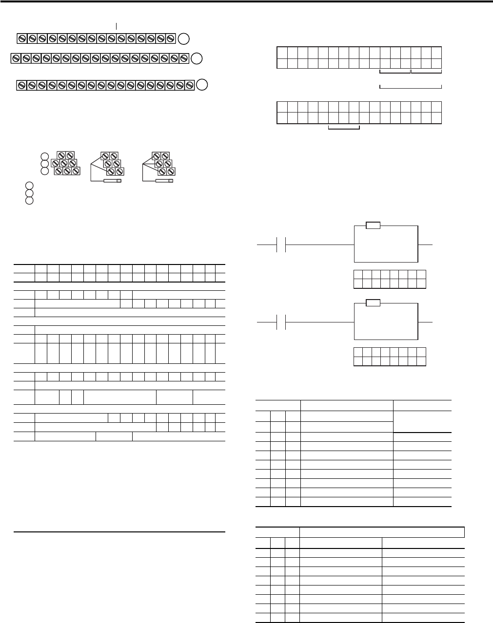
Fill File
Source
Destination #0:010
Length 1
FLL
1794-IB16XT
I:000
Write filter time on system startup.
Write FT on
complement of
input module.
= 44 Octal or
36 Decimal
00
76543210
100100
44707
Fill File
Source
Destination #0:010
Length 1
FLL
1794-IB10XOB16XT
I:000
Write filter time on system startup.
Write FT on
complement of
input module.
= 5 Octal or
5 Decimal
00
12 11 10 9 8 7 6 5
101
44709