
Installation Instructions Owner's manual


6
Publication 1794-IN094B-EN-P - April 2004
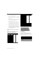
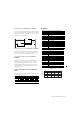
Derating Curve for the 1794-OB16P
Specifications - 16 Output Modules 1794-OB16, -OB16P and
-OB16PK
1794-OB16 1794-OB16P, -OB16PK
Number of Outputs 16, nonisolated, sourcing
Module Location Cat. No. 1794-TB2, -TB3, -TB3S
On-state Current 1.0mA minimum per channel
500mA maximum per channel
Output Current Rating 8.0A (16 outputs @ 0.5A)
Surge Current 2A for 50ms, repeatable every 2s 1.5A for 50ms, repeatable every 2s
Off-state Leakage 0.5mA maximum
On-state Voltage Drop 0.5V dc maximum
Isolation Voltage Tested at 850V dc for 1s between
user and system
No isolation between individual
channels
Tested at 2121V dc for 1s between
user and system
No isolation between individual
channels
Output Signal Delay Off to On - 0.5ms maximum
On to Off - 1.0ms maximum
Flexbus Current 80mA 60mA
Power Dissipation 5.3W maximum @ 31.2V dc 5.0W maximum @ 31.2V dc
Thermal Dissipation Maximum 18.1 BTU/hr @ 31.2V dc Maximum 17.0 BTU/hr @ 31.2V dc
Indicators (field side
indication, logic driven)
16 yellow status indicators
Fusing Module outputs are not fused.
Fusing is recommended. If fusing is
desired, you must provide external
fusing. Use SAN-O MQ4-800mA
fuses
Outputs are electronically
protected.
Specifications - 24V dc 32 Output Module, Cat. No. 1794-OB32P
Number of Outputs 32 (2 groups of 16) nonisolated within groups, sourcing
Module Location Cat. No. 1794-TB32, -TB32S
On-state Current 1.0mA minimum per channel; 500mA maximum per channel
Output Current Rating 14A maximum per module (6A total for channels 0-15; 8A total for
channels 16-31)
Surge Current 2A for 50ms, repeatable every 2s
Off-state Leakage 0.5mA maximum
On-state Voltage Drop 0.5V dc maximum
Isolation Voltage Tested at 2121V dc for 1s between user and system
No isolation between individual channels
Output Signal Delay Off to On - 0.5ms maximum
On to Off - 1.0ms maximum
Flexbus Current 80mA
Power Dissipation 5.3W maximum @ 31.2V dc
Thermal Dissipation Maximum 18.1 BTU/hr @ 31.2V dc
Indicators (field side
indication, logic driven)
32 yellow status indicators
Fusing Outputs are electronically protected.
General Specifications
On-state Voltage Range 10V dc minimum (1794-OB8EP - 19.2V dc minimum)
24V dc nominal
31.2V dc maximum
Off-state Voltage 31.2V dc maximum
Terminal Base Screw
Torque
7 pound-inches (0.8Nm)
1794-TBN - 9 pound-inches (1.0Nm)
External dc Power
‘Supply Voltage
Voltage Range
Supply Current
24V dc nominal
1794-OB8, -OB16, -OB16P, -OB32P - 10 to 31.2V dc (includes 5% ac ripple)
1794-OB8EP - 19.2 to 31.2V dc (includes 5% ac ripple)
1794-OB8 - 25mA @ 24V dc (10 to 35mA)
1794-OB8EP - 80mA @ 24V dc
1794-OB16 - 49mA @ 24V dc (20-65mA)
1794-OB16P - 60mA @ 24V dc (25 to 75mA) See derating curve.
1794-OB32P - 219mA @ 24V dc (104mA @ 10V dc;-278mA @ 31.2V dc)
Dimensions (with
module installed)
3.7H x 3.7W x 2.7D inches
94H x 94W x 69D mm
Keyswitch Position 2
Environmental Conditions
Operating
Temperature
IEC 60068-2-1 (Test Ad, Operating Cold),
IEC 60068-2-2 (Test Bd, Operating Dry Heat),
IEC 60068-2-14 (Test Nb, Operating Thermal Shock):
0 to 55°C (32 to 131°F)
Storage
Temperature
IEC 60068-2-1 (Test Ab, Un-packaged Non-operating Cold),
IEC 60068-2-2 (Test Bb, Un-packaged Non-operating Dry Heat),
IEC 60068-2-14 (Test Na, Un-packaged Non-operating Thermal Shock):
–40 to 85°C (–40 to 185°F)
Relative Humidity IEC 60068-2-30 (Test Db, Un-packaged Non-operating
Damp Heat):
5 to 95% noncondensing
Vibration IEC60068-2-6 (Test Fc, Operating):
5g @ 10-500Hz
Shock IEC60068-2-27 (Test Ea, Unpackaged shock):
Operating 30g
Non-operating 50g
Emissions CISPR 11:
Group 1, Class A (with appropriate enclosure)
ESD Immunity IEC 61000-4-2:
4kV contact discharges
8kV air discharges
Radiated RF
Immunity
IEC 61000-4-3:
10V/m with 1kHz sine-wave 80%AM from 30MHz to 1000MHz
EFT/B Immunity IEC 61000-4-4:
±2kV at 5kHz on signal ports
Surge Transient
Immunity
IEC 61000-4-5:
±1kV line-line(DM) and ±2kV line-earth(CM) on signal ports
Conducted RF
Immunity
IEC 61000-4-6:
10Vrms with 1kHz sine-wave 80%AM from 150kHz to 30MHz
Enclosure Type Rating None (open-style)
Conductors Wire Size
Category
1
12AWG (4mm
2
) stranded copper wire rated at 75°C or higher
3/64 inch (1.2mm) insulation maximum
2
Certifications (when
product is marked)
2
UL UL Listed Industrial Control Equipment (all)
CULUS UL Listed Industrial Control Equipment, certified for US and
Canada (1794-OB32P)
CULUS UL Listed for Class I, Division 2, Groups A, B, C and D
Hazardous locations , certified for US and Canada (1794-OB8)
CSA CSA certified for Class I, Division 2, Groups A, B, C and D
Hazardous locations (1794-OB8, -OB8EP, -OB16, -OB16P)
EEx
2
European Union 94/9/EEC ATEX Directive, compliant with:
EN 50021; Potentially Explosive Atmospheres,
Protection “n”(Zone 2) - (1794-OB8, -OB8EP, -OB16, -OB16P)
CE
2
European Union 89/336/EEC EMC Directive, compliant with:
EN 61000-6-4; Industrial Emissions
EN 50082-2; Industrial Immunity
EN 61326; Meas./Control/Lab., Industrial Requirements
EN 61000-6-2; Industrial Immunity (all)
C-Tick
2
- Australian Radiocommunications Act compliant with
AS/NZS CISPR 11, Industrial Emissions (all)
1 You use this category information for planning conductor routing as described in Allen-Bradley
publication 1770-4.1, Industrial Automation Wiring and Grounding Guidelines.
2 For the latest up-to-date information, see the Product Certification link at www.ab.com for Declarations of
Conformity, Certificates and other certification details. For notification of any additional release notes, refer to
www.ab.com/manuals/.
0
15
10
25
20
30
31.2
10 20 30 40 50 55 60
Ambient Temperature
o
C
The area within the curve represents the safe operating range for the module
under various conditions of user supplied 24V dc supply voltages and ambient
temperatures.
= Normal mounting safe operating range, (includes ).
= Other mounting positions (including inverted horizontal) safe operating range
3732
28.5
27.5
Normal Mounting – Horizontal
Other Mounting (including Vertical, and Inverted Horizontal
Mounting)
in
V
On-State
Voltage
(V dc)