
Installation Instructions Owner's manual


4
Publication 1794-IN094B-EN-P - April 2004
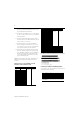
4. Connect individual output wiring (OUT16 to
OUT31) to numbered terminals on the 16-33 row
(B) as indicated in the table below.
5. Connect the associated power to the +V2 terminal
(43, 45, 47 or 49) on the 34-51 row (C) as indicated
in the table below.
6. Connect the associated output common (-V2)for
OUT16 to OUT31 to COM2 (terminals 44, 46, 48
or 50) on the 34 to 51 row (C).
7. If continuing power to the next terminal base,
connect a jumper from terminal 35, 37, 39 or 41
(+V1) and 43, 45, 37 or 49 (+V2) on this base unit
to the power terminal on the next base unit.
8. If continuing output common return to the next
base unit, connect a jumper from terminal 36, 38,
40 or 42 (COM1) and 44, 46, 48 or 50 (COM2) on
this base unit to common on the next base unit
(refer to the installation instructions for the next
type of terminal base unit).
Note: Total current draw through the terminal base is
limited to 10A. Separate power connections may be
necessary.
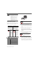
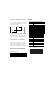
Wiring Connections for the 1794-OB32P (used with
1794-TB32 or -TB32S Terminal Base Unit)
1794-TB32 and -TB32S Terminal Base Wiring for 1794-OB32P
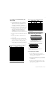
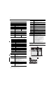
Configuring Your 1794-OB8EP and -OB8EPK Output Module
You configure your output module by setting bits in the
configuration word (see below).
Output Output Terminal Common Power
Output 0 A-0 Connect common
to terminals 36,
38, 40 and 42
Connect power
to terminals 35,
37, 39 and 41
Output 1 A-1
Output 2 A-2
Output 3 A-3
Output 4 A-4
Output 5 A-5
Output 6 A-6
Output 7 A-7
Output 8 A-8
Output 9 A-9
Output 10 A-10
Output 11 A-11
Output 12 A-12
Output 13 A-13
Output 14 A-14
Output 15 A-15
Output 16 B-17 Connect common
to terminals 44,
46, 48 and 50
Connect power
to terminals 43,
45, 47 and 49
Output 17 B-18
Output 18 B-19
Output 19 B-20
Output 20 B-21
Output 21 B-22
Output 22 B-23
Output 23 B-24
Output 24 B-25
Output 25 B-26
Output 26 B-27
Output 27 B-28
Output 28 B-29
Output 29 B-30
Output 30 B-31
Output 31 B-32
For Outputs 0 thru 15, use +V1 and COM1
+V1 dc power Power terminals 35, 37, 39 and 41
Com1 dc Return Common terminals 36, 38, 40 and 42
For Outputs 16 thru 31, use +V2 and COM2
+V2 dc power Power terminals 43, 45, 47 and 49
Com2 dc Return Common terminals 44, 46, 48 and 50
Dec. 15 14 13 12 11 10 9 8 7 6 5 4 3 2 1 0
Oct. 17 16 15 14 13 12 11 10 7 6 5 4 3 2 1 0
Read F7 F6 F5 F4 F3 F2 F1 F0 Reserved (see note)
Write Not used FR O
7
O
6
O
5
O
4
O
3
O
2
O
1
O
0
Write
Where: O = Output - O0 corresponds to output 0, O1 corresponds to output 1, etc.
F = Overload fault bits - 1 = fault present; 0 = no fault
FR = Fault reset bit - 1 = reset output; 0 = no change
Note: The unused lower byte in read word 1 floats during operation. Do not use this byte for fault status.
See Programming below.
Output Output Terminal Common Power
17 18 19 20 21 22 23 24 25 26 27 28 29 30 31 32 33
0 1 2 3 4 5 6 7 8 9 10 11 12 13 14 15
16
35 36 37 38 39 40 41 42 43 44 45 46 47 48 49 50 51
34
NC
+V2 = Terminals 43, 45, 47 and 49
Outputs
Outputs
+V1 COM1 +V1 COM1 +V1 COM1 +V1 COM1 +V2 COM2 +V2 COM2 +V2 COM2 +V2 COM2 NC
+V1 = Terminals 35, 37, 39 and 41
COM1 = Terminals 36, 38, 40 and 42
NC = No connections (terminals 16, 33, 34 and 51)
COM2 = Terminals 44, 46, 48 and 50
NC NC
(1794-TB32 shown)
A
B
C