
Installation Instructions Owner's manual


3
Publication 1794-IN094B-EN-P - April 2004
Connecting Wiring for the 1794-OB8, -OB8EP, -OB8EPK, -OB16,
-OB16P and -OB16PK
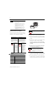
1. Connect individual output wiring to numbered
terminals on the 0-15 row (A) as indicated in the
table below (1794-OB8 - Terminals 0-7;
1794-OB16 and -OB16P(K) - terminals 0-15;
1794-OB8EP(K) - even numbered terminals 0-14).
2. Connect the associated -V output common to the
corresponding terminal on the 16-33 row (B) for
each output as indicated in the table below.
(Commons are internally connected together.)
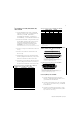
1794-OB8EP(K) - connect associated output common to
odd-numbered terminals on row A or associated terminals on row B.
3. Connect +V dc power to terminal 34 on the 34-51
row (C).
4. Connect -V dc common to terminal 16 on the
16-33 row (B).
5. If daisychaining power to the next terminal base,
connect a jumper from terminal 51 (+V dc) on this
base unit to terminal 34 on the next base unit.
6. If continuing -V dc common to the next base unit,
connect a jumper from terminal 33 (common) on
this base unit to terminal 16 on the next base unit.
Wiring Connections for the 1794-OB8, -OB16, -OB16P and
-OB16PK using the 1794-TB2, -TB3, or -TB3S
Wiring Connections for the 1794-OB8EP and -OB8EPK
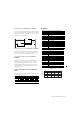
1794-TB2, -TB3 and -TB3S Terminal Base Wiring for 1794-OB8,
-OB8EP, -OB8EPK, -OB16, -OB16P and -OB16PK
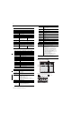
1794-TBN Terminal Base Wiring for the 1794-OB8EP
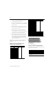
Connecting Wiring for the 1794-OB32P
1. Connect individual output wiring (OUT0 to
OUT15) to numbered terminals on the 0-15 row
(A) as indicated in the table below.
2. Connect the associated power to the +V1 terminal
(35, 37, 39 or 41) on the 34-51 row (C) as indicated
in the table below.
3. Connect the associated output common (-V1)for
OUT0 to OUT15 to COM1 (terminal 36, 38, 40 or
42) on the 34 to 51 row (C).
Output
1
Output Terminal Common Terminal
Output 0 A-0 B-17
Output 1 A-1 B-18
Output 2 A-2 B-19
Output 3 A-3 B-20
Output 4 A-4 B-21
Output 5 A-5 B-22
Output 6 A-6 B-23
Output 7 A-7 B-24
Output 8 A-8 B-25
Output 9 A-9 B-26
Output 10 A-10 B-27
Output 11 A-11 B-28
Output 12 A-12 B-29
Output 13 A-13 B-30
Output 14 A-14 B-31
Output 15 A-15 B-32
+V dc C-34 thru C-51 (C-34 and C-51 for 1794-TB2)
Common B-16 thru B-33
1
1794-OB8 - Outputs 0 thru 7; 1794-OB16, -OB16PK and -OB16P- Outputs 0
thru 15
1794-TB2, -TB3, TB3S 1794-TBN
Output Output
Terminal
Common
Terminal
1
Output
Terminal
Common
Terminal
2
Output 0 A-0 A-1/B-17 B-0 C-1
Output 1 A-2 A-3/B-18 B-2 C-3
Output 2 A-4 A-5/B-19 B-4 C-5
Output 3 A-6 A-7/B-20 B-6 C-7
Output 4 A-8 A-9/B-21 B-8 C-9
Output 5 A-10 A-11/B-22 B-10 C-11
Output 6 A-12 A-13/B-23 B-12 C-13
Output 7 A-14 A-15/B-24 B-14 C-15
+V dc C-34 thru C-51 (C-34 and C-51 for 1794-TB2, -TBN)
Common B-16 thru B-33 (B-16 and B-33 for 1794-TBN)
1
1794-TB2, -TB3, -TB3S - A-1, A-3, A-5, A-7, A-9, A-11, A-13 and A-15 are connected
together inside the module to 24V dc common.
2
1794-TBN - C-1, C-3, C-5, C-7, C-9, C-11, C-13 and C-15 are connected together inside the
module to 24V dc common.
17 18 19 20 21 22 23 24 25 26 27 28 29 30 31 32 33
0 1 2 3 4 5 6 7 8 9 10 11 12 13 14 15
16
35 36 37 38 39 40 41 42 43 44 45 46 47 48 49 50 51
34
Outputs
Commons
(1794-TB3 shown)
Connect -V (Supply Common) to terminal B-16
Connect +V (Supply +Voltage) to terminal C-34
-V
Voltage
In +V
Voltage
Out +V
Voltage
Terminals 35 thru 50 not available on 1794-TB2
A
B
C
Common
-V
Common
(Use B-33 and C-51 for daisy-chaining to next terminal base unit.)
Total current draw through the terminal base is limited to 10A. Separate powe
r
connections to each terminal base may be necessary.
16
0
1
2
3
4
5
6
7
8
9
10
11
12
13
14
15
51
33
34
+V
COM
+V
COM
B
C
Even Numbered I/O Terminals 0 thru 14
Odd Numbered I/O Terminals 1 thru 15
C
onnect -V (Supply Common) to terminal B-16
C
onnect +V (Supply +Voltage) to terminal C-34
(
Use B-33 and C-51 for daisy-chaining to next terminal base unit.)
Total current draw through the terminal base is limited to 10A. Separate pow
er
connections to each terminal base may be necessary.