
User Manual Owner's manual

Publication 1794-UM061A-EN-P - July 2006
Interpret the Indicators 107
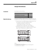
1794-OB16D Diagnostic
Functional Details
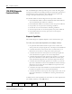
Two module indicators and four diagnostic bits report fault conditions:
• the module fault indicator illuminates red and the individual faulted
channel indicator also illuminates red under output ON state open and
output OFF state short conditions.
• the module fault indicator illuminates red for reverse user power
conditions.
• the open bit is set for open load and wiring conditions in the output
OFF state.
• the short bit is set for shorted load and wiring conditions in the output
ON state.
• the reverse power bit is set for reverse polarity user power conditions.
• the module fault bit is set for any open, short or reverse power
conditions detected.
The module’s diagnostic capability depends on whether the output is energized
(ON) or de-energized (OFF).
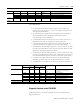
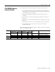
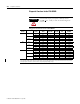
Fault Device/Output Status
Fault
Indicators
Error Bit
Status
Conditions
Field Device Status Output Status Module Fault Channel
Fault
Open OFF OFF Red Red Open wire
& Module
No current in output terminal-
missing dummy resistor or field device,
cut output channel or Common wire
OFF ON OFF Yellow None Can’t detect an open in the ON-state
Short OFF ON Red Red Short & Module Short - output to Common
OFF OFF OFF OFF None Can’t detect a short in the OFF-state
Reverse
User Power
OFF OFF or ON Red OFF Reverse & Module User power supply wiring is reversed