FLEX I/O Diagnostic Modules Catalog Numbers 1794-IB16D, 1794-OB16D User Manual
Important User Information Solid state equipment has operational characteristics differing from those of electromechanical equipment. Safety Guidelines for the Application, Installation and Maintenance of Solid State Controls (publication SGI-1.1 available from your local Rockwell Automation sales office or online at http://literature.rockwellautomation.com) describes some important differences between solid state equipment and hard-wired electromechanical devices.
Table of Contents Preface Purpose of This Manual. . . . . . . . . . . . . . . . . . . . . . . . . . . . . . . . . . . . . . 5 Important Warnings and Cautions . . . . . . . . . . . . . . . . . . . . . . . . . . . . . 5 North American Hazardous Location Approval . . . . . . . . . . . . . . . 7 Related Products and Documentation . . . . . . . . . . . . . . . . . . . . . . . . . . 8 Chapter 1 1794 FLEX I/O Diagnostic Digital Modules Overview Introduction . . . . . . . . . . . . . . . . . . . . . . . . . . . .
Table of Contents iv Chapter 4 Configuring Modules for Communication on a Remote I/O Network Chapter Objectives. . . . . . . . . . . . . . . . . . . . . . . . . . . . . . . . . . . . . . . . . 33 Add a 1756-DHRIO Module. . . . . . . . . . . . . . . . . . . . . . . . . . . . . . . . . 34 Add a 1794 Remote Adapter Module . . . . . . . . . . . . . . . . . . . . . . . . . . 37 Configure Digital Modules. . . . . . . . . . . . . . . . . . . . . . . . . . . . . . . . . . .
Table of Contents v Add Distributed I/O . . . . . . . . . . . . . . . . . . . . . . . . . . . . . . . . . . . . . . . 88 Add a Module. . . . . . . . . . . . . . . . . . . . . . . . . . . . . . . . . . . . . . . . . . 89 Download the Program to the Controller. . . . . . . . . . . . . . . . . . . . . . . 89 Access Distributed I/O . . . . . . . . . . . . . . . . . . . . . . . . . . . . . . . . . . . . . 91 General Information About IP Addresses . . . . . . . . . . . . . . . . . . . . . .
Table of Contents vi Index Publication 1794-UM065B-EN-E - July 2006 1794-OB16P 24V DC 16 Output Module . . . . . . . . . . . . . . . . . . 121 1794-OB32P 24V DC 32 Output Module . . . . . . . . . . . . . . . . . . 122 1794-OV16 24V DC 16 Sink Output Module . . . . . . . . . . . . . . . 123 1794-OV16P 24V DC 16 Sink Output Module . . . . . . . . . . . . . . 123 1794-IC 48V DC 16 Input Module. . . . . . . . . . . . . . . . . . . . . . . . 124 1794-OC 48V DC 16 Output Module . . . . . . . . . . . . . . . .
Preface Purpose of This Manual Important Warnings and Cautions This manual provides information on installation, setting, and reading your diagnostics on the 1794-IB16D and the 1794-OB16D Diagnostic modules.
6 Preface WARNING When you insert or remove the module while backplane power is on, an electrical arc can occur. This could cause an explosion in hazardous location installations. Be sure that power is removed or the area is nonhazardous before proceeding. ATTENTION FLEX I/O is grounded through the DIN rail to chassis ground. Use zinc plated yellow-chromate steel DIN rail to assure proper grounding.
Preface 7 North American Hazardous Location Approval The 1794-IB16D and 1794-OB16D diagnostic modules are North American Hazardous Location approved. The following information applies when operating this equipment in hazardous locations: Products marked “CL I, DIV 2, GP A, B, C, D” are suitable for use in Class I Division 2 Groups A, B, C, D, Hazardous Locations and nonhazardous locations only.
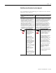
8 Preface Related Products and Documentation Catalog Number For additional information on FLEX I/O systems and modules, refer to the following documents: Voltage Description Publications Installation Instructions 1794 1794–ACN 24V dc 1794-AENT 1794 FLEX I/O Selection Guide 1794–SG002 ControlNet Adapter 1794–IN101 EtherNet/IP Adapter 1794-IN082 User Manual ENET-UM001 1794–ACNR 24V dc Redundant Media ControlNet Adapter 1794–IN101 1794–ACN15 24V dc ControlNet Adapter 1794-IN101 1794–AC
Preface Catalog Number Voltage Description 9 Publications Installation Instructions User Manual 1794-IE12 24V dc 12 Input Analog Module 1794-IN106 1794-OE12 24V dc 12 Output Analog Module 1794-IE8XOE4 24V dc 8 Input/4 Output Analog Module 1794-IE8H 24V dc 8 HART Input Module 1794-IN108 1794-OE8H 24V dc 8 HART Output Module 1794-IN109 1794–IR8 24V dc 8 RTD Input Analog Module 1794-IN021 1794–IT8 24V dc 8 Thermocouple Input Module 1794–IRT8 24V dc 8 Thermocouple/RTD Input Mod
10 Preface Catalog Number Voltage Description Publications Installation Instructions 1794–TB2 Cage Clamp Terminal Base 1794-IN092 1794–TB3 Cage Clamp Terminal Base 1794–TB3S Spring Clamp Terminal Base Unit 1794–TB3T Temperature Terminal Base Unit 1794–TB3TS Spring Clamp Temperature Base Unit 1794–TB3G Terminal Base Unit 1794–TB3GS Spring Clamp Terminal Base Unit 1794–TB32 Cage Clamp Terminal Base Unit 1794–TB32S Spring Clamp Terminal Base Unit 1794–TBN Terminal Base Unit 1794–TBNF
Preface Catalog Number Voltage Description 11 Publications Installation Instructions 1797–BIC See note I.S. Bus Isolator 1797-5.13 1797–CEC See note FLEX Ex Bus Connector 1797-5.13 User Manual Note: Intrinsically Safe Voltage For more information on DeviceNet modules in Logix5000 systems, see publication DNET-UM004, DeviceNet Modules in Logix5000 Systems. For more information on ControlNet modules in Logix5000 systems, see publication CNET-UM001, ControlNet Modules in Logix5000 Systems.
12 Preface Notes: Publication 1794-UM065B-EN-E - July 2006
Chapter 1 1794 FLEX I/O Diagnostic Digital Modules Overview Introduction General Description In this chapter, you will learn about the diagnostic input module, cat. no. 1794-IB16D, and the diagnostic output module, cat. no. 1794-OB16D. Topic See Page General Description 13 Install Your Digital Input or Output Module 16 This chapter contains an overview of the FLEX I/O diagnostic digital modules, the 1794-IB16D input module and 1794-OB16D output module.
14 1794 FLEX I/O Diagnostic Digital Modules Overview Network Compatibility You can use the diagnostic modules with ControlNet, DeviceNet, EtherNet/IP, or remote I/O networks. Usage Limitations Network 1794-IB16D 1794-OB16D Remote I/O Compatible with 1794-ASB series E (or higher) and 1794-ASB2 series D (or higher) remote I/O adapters. Compatible with 1794-ASB series D (or higher) and 1794-ASB2 series C (or higher) remote I/O adapters. DeviceNet No limitations or constraints.
94 FLEX I/O Diagnostic Digital Modules Overview 15 Capabilities of the 1794-IB16D include: • • • • • 61131-2 Type 3 compatible sinking inputs. interface with PNP sourcing sensors. 10-31.2V dc operating range. provides up to 50 mA to power an attached sensor. detects for an open wire condition down to 50 μA. You need a dummy resistor to mask the channel diagnostic function for each unused sensor port.
16 1794 FLEX I/O Diagnostic Digital Modules Overview Install Your Digital Input or Output Module To install a digital diagnostic module, follow these steps: ✓ Installation Step ❑ 1. Mount the terminal base unit See installation instructions 1794-IN096. ❑ 2. Install the module in the terminal base unit See installation instructions 1794-IN096. ❑ 3. Connect the wiring to the terminal base unit See installation instructions 1794-IN096.
1794 FLEX I/O Diagnostic Digital Modules Overview 17 1794-TB32 and 1794-TB32S Terminal Base Wiring for the 1794-IB16D 0 1 2 3 4 5 6 7 8 9 10 11 12 13 14 15 A 0 1 17 16 2 18 3 19 4 20 5 6 7 8 9 10 11 Inputs Channels 0-15 21 22 23 24 25 26 27 12 28 13 29 14 30 15 31 32 33 B NC 0 34 1 35 2 36 3 4 5 6 7 8 9 10 11 12 13 Sensor Power Terminals for Channels 0-15 37 38 39 40 41 42 43 44 45 46 47 48 14 NC 15 49 50 51 C NC +V1 COM
18 1794 FLEX I/O Diagnostic Digital Modules Overview 1794-TB2, -TB3, and -TB3S Terminal Base Wiring for the 1794-OB16D Outputs 0 1 2 3 4 5 6 7 8 9 10 11 12 13 14 15 A 17 16 18 19 20 21 22 23 24 25 26 27 28 29 30 31 32 33 B -V Common 34 Commons 35 36 37 38 39 40 41 42 -V Common 43 44 45 46 47 48 49 50 51 C Voltage In +V Terminals 35 through 50 not available on 1794-TB2 Voltage Out +V Voltage -V (Supply Common) = Terminals B-16 through B-33.
2 About the FLEX I/O Diagnostic Input Module Introduction About the 1794-IB16D Diagnostic Input Module In this chapter, you will learn about the diagnostic input module, cat. no. 1794-IB16D.
20 About the FLEX I/O Diagnostic Input Module Wiring Input Sensors You must use a 1794-TB32 or 1794-TB32S terminal base unit with the 1794-IB16D diagnostic input module. See installation instructions ldkg df;l 1794-IN096 for complete information.
About the FLEX I/O Diagnostic Input Module 21 . . The module monitors current and voltage at each input channel sensor power terminal, and monitors the user supply for reverse user supply voltage. The figure below shows the location of these fault monitors in the 1794-IB16D diagnostic input module.
22 About the FLEX I/O Diagnostic Input Module Sensor Power Open and Short Circuit Detection The sensor-power open-wire current monitor detects a fault condition if the sensor-power current drops below 50 μA. Sensor-power shorts are protected by the positive temperature coefficient (PTC) resistor in series with each sensor power output (16 total). For overcurrents or shorts, the PTC resistor heats up, the resistance increases and the sensor power output opens, similar to a fuse opening.
About the FLEX I/O Diagnostic Input Module 23 User Power Supply Reverse Voltage Detection If the external user power supply is miswired (incorrect polarity), the module is protected and reports a reverse user voltage fault. The reverse voltage condition must be at least -10V to detect a fault. The module’s Fault indicator turns red and the reverse fault bit is set. The module error bit is also set.
24 About the FLEX I/O Diagnostic Input Module Module Limitations Input Voltage Derating You must derate the input voltage applied to each input channel, based on operating ambient temperature, to keep module power dissipation within an acceptable level. 30 25 Input Voltage (V) 31.2 26.
About the FLEX I/O Diagnostic Input Module 25 Unused Sensor Power Ports You must connect dummy resistors to unused Sensor Power ports to mask the diagnostic function. If external resistors are not used, the module's sensing circuitry will not detect the intended voltage or current and not report that a fault exists. The module’s fault and open-channel indicators light, and the module’s open and module error bits are set, thus rendering fault detection of the remaining channels useless.
26 About the FLEX I/O Diagnostic Input Module Configure Your Diagnostic Input Module Dec. Oct. Read 1 Read 2 Write 1 Where: The configuration and input filter selection table are shown below.
Chapter 3 About the FLEX I/O Diagnostic Output Module Introduction About the 1794-OB16D Diagnostic Output Module In this chapter, you will learn about the diagnostic output module, cat. no. 1794-OB16D.
28 About the FLEX I/O Diagnostic Output Module Wiring Output Loads You can use the 1794-OB16D diagnostic module with the 1794-TB2, 1794-TB3, or 1794-TB3S terminal base units.
About the FLEX I/O Diagnostic Output Module 29 You must connect dummy resistors to unused sensor power ports to mask the diagnostic function. If these external resistors are not used, the module’s sensing circuitry will not detect the intended voltage or current and signal a module fault. The channel fault indicator and the module’s fault indicator will light, and the module’s open and error bits are set, thus rendering fault detection of the remaining channels useless.
30 About the FLEX I/O Diagnostic Output Module The output open-wire current monitor detects a fault condition if the output OFF-state current drops below 0.1 mA. Output channel shorts are protected by a current limit and over-temperature thermal sensor built into the output device. For overcurrents, the output device’s internal current limit is tripped and the output voltage begins to collapse.
About the FLEX I/O Diagnostic Output Module 31 External Power Supply Reverse Voltage If the external user power supply polarity is incorrect, the module is protected and reports a reverse user voltage fault. The reverse voltage condition must be at least -10V to detect a fault. The modules fault indicator turns red and the reverse fault bit is set. The module error bit is also set.
32 About the FLEX I/O Diagnostic Output Module • Channel I/O Status- This indicator displays the on/off state of each output channel, as well as channel wiring fault conditions: – Off indicates the output channel is off with no faults. – Yellow indicates the output channel is on with no faults. – Red indicates either an output channel open or short condition. • Module Fault Status- This indictor turns red for individual output channel opens, shorts or module reverse power conditions.
Chapter 4 Configuring Modules for Communication on a Remote I/O Network Chapter Objectives This chapter provides you with the RSLogix 5000 software steps you need to configure a 1756-DHRIO module, remote adapter module and block transfer and digital modules for use with a ControlLogix controller on a Remote I/O (RIO) network.
34 Configuring Modules for Communication on a Remote I/O Network Add a 1756-DHRIO Module The 1756-DHRIO module provides two configurable channels that can either send and receive messages over DH+ or scan remote I/O devices. When a channel is configured for remote I/O, the 1756-DHRIO module is designed to function as a remote I/O scanner for a ControlLogix controller.
Configuring Modules for Communication on a Remote I/O Network 35 4. Configure the 1756-DHRIO module parameters. A. Define the following parameters: • Name • Slot • Type • Baud Rate • Revision • Electronic Keying • Open Module Properties Refer to the 1756-DHRIO Module Properties Dialog Box table for information on how to fill-in the dialog box. Click OK. 1756-DHRIO Module Properties Dialog Box In This Field: Do the Following: Name Type a name for the module (i.e.,DHRIO_module_in_slot_1).
36 Configuring Modules for Communication on a Remote I/O Network 5. Specify parameters on 1756-DHRIO Connection tab screen. A. • • • Define the following parameters: Requested Packet Interval Inhibit Module Major Fault on Controller if Connection Fails While in Run Mode Refer to the Connection Tab Screen table for information on how to fill-in the dialog box. B. Click OK. The 1756-DHRIO module is now listed in the controller organizer .
Configuring Modules for Communication on a Remote I/O Network Add a 1794 Remote Adapter Module 37 The following steps show you how to add a 1794-ASB module to your project and set the configuration parameters. 1. Add the 1794-ASB adapter module to the controller organizer.: A. From controller organizer, select the channel you are using for your configuration then, right-click to display the pull-down menu. In this example, only channel B is connected to remote I/O.
38 Configuring Modules for Communication on a Remote I/O Network 1794-ASB Adapter Module Properties Dialog Box In This Field: Do the Following: Name Type a name for the adapter module. We recommend that you use a name that identifies the I/O type for the adapter module you are configuring. Rack # (Octal) Select the Remote I/O network rack ID for the rack. Starting Group Select the starting group of this rack based on the switch setting of the 1794-ASB adapter module.
Configuring Modules for Communication on a Remote I/O Network 39 1794-ASB Connection Tab Configuration Parameters In This Field: Do the Following: Requested Packet Interval (RPI) Select the rate at which the DHRIO module sends discrete data from the I/O rack to the controller. The rate of data exchange is directly related to the configured baud rate for the 1756-DHRIO module. If the baud rate of the scanner is configured for: The scan rate per adapter equals: 57.6 Kbaud 8ms 115.2 Kbaud 5ms 230.
40 Configuring Modules for Communication on a Remote I/O Network Configure Digital Modules Although not required, when the module is in the I/O configuration, you gain these advantages: • It is easier to complete the communication path to the module. • The I/O configuration provides documentation about the module. For example, once you add an I/O module to the controller organizer window you can use the Browse button on the Communication Tab to select the path for the block transfer message.
Configuring Modules for Communication on a Remote I/O Network 41 2. Configure parameters for the RIO Block Transfer module. A. Define the following parameters: • Name • Group • Slot • Open Module Properties Refer to the 1756-DHRIO Block Module Transfer Parameters table for additional information. B. Click OK. C. Repeat steps A and B for the Diagnostic output module. The I/O modules are added to the controller organizer tree.
42 Configuring Modules for Communication on a Remote I/O Network Create a Block Transfer (Read or Write) Message Instruction Analog and specialty I/O modules are block transfer I/O modules. The size of the data that is transferred from the modules to the controller is larger than the space that RSLogix 5000 software has allocated in the controller memory.
Configuring Modules for Communication on a Remote I/O Network 43 2. Add a Message instruction (MSG). A. Click on the Input/Output instruction set tab. B. Click on MSG to insert the message instruction. 3. Add a new tag to the MSG instruction. A. Right-click on the ? in the MSG instruction. B. Click on New Tag in the pull-down menu. 4. Name and define the parameters for the MSG tag. A.
44 Configuring Modules for Communication on a Remote I/O Network 5. Define the Block Transfer Configuration Tab parameters A. Define the following message configuration fields: • Message Type • Number of Elements • Destination Element or New Tag (Block Transfer Read only) • Source Element (Block Transfer Write only) Refer to the Message Configuration Parameters - Block Transfer Read or Write table below for additional information. B. Click on the Communication tab.
Configuring Modules for Communication on a Remote I/O Network 45 6. Configure the Communication Tab for the MSG Instruction. A. Define the following communication fields: • Path • Module Address • Cache Connections B. Click OK. Communication Parameters Path Click on Browse to see a list of the I/O modules in the system. To be able to choose a path for your message instruction using the Browse button, you had to previously configure the I/O module.
46 Configuring Modules for Communication on a Remote I/O Network Ladder Logic Examples The following illustration provide you with a ladder logic examples for 1794 diagnostic modules. The example is typical ControlLogix software ladder rungs for block transfer message instructions Ladder Logic Example for 1794 Diagnostic Modules.
Chapter 5 Configure FLEX I/O Digital Modules on a DeviceNet Network How to Use This Chapter This chapter provides basic information on how to use a 1794-ADN FLEX I/O adapter to connect 1794 FLEX I/O digital modules to a DeviceNet network.
48 Configure FLEX I/O Digital Modules on a DeviceNet Network Add the Scanner to the I/O Configuration of the Controller Using RSLogix 5000 Software To access the data of your network, add the scanner to the I/O configuration of the controller.
Configure FLEX I/O Digital Modules on a DeviceNet Network 49 Set the status size for a scanner If you want this information: Set the Status Which gives you: Size to (DINTs): Member: Data Type 10 ScanCounter DINT DeviceFailureRegister SINT[8] AutoverifyFailureRegister SINT[8] DeviceIdleRegister SINT[8] ActiveNodeRegister SINT[8] StatusDisplay SINT[4] ScannerAddress SINT status code of scanner ScannerStatus SINT address with an error: ScrollingDeviceAddress SINT ScrollingDeviceStatus
50 Configure FLEX I/O Digital Modules on a DeviceNet Network Add the Scanner to the I/O Configuration Folder CompactLogix scanner ControlLogix, FlexLogix, and SoftLogix5800 scanners 1. Right-click and choose New Module. EtherNet/IP to DeviceNet linking device ControlNet to DeviceNet linking device 2. Choose the type of scanner. 3. Select the major revision of the scanner.
Configure FLEX I/O Digital Modules on a DeviceNet Network 51 Define the Properties of the Scanner 1. Specify the general properties (name, slot, sizes, etc.). 2. Choose Next. 3. Choose Next. 4. Choose Browse and find the RSNetWorx configuration file for the network (.dnt file). The default path for the file is …\Program Files\Rockwell Software\RSNetWorxII\Networks. 5. Choose Finish.
52 Configure FLEX I/O Digital Modules on a DeviceNet Network Determine the Address of DeviceNet Data When you add the scanner to the I/O configuration of the controller, RSLogix 5000 software automatically creates a set of tags for the input, output, and status data of the network: input data from the scanner output data for the scanner status data from the scanner The tags for your DeviceNet data follow this format: The scanner memory uses this format: slot type .
Configure FLEX I/O Digital Modules on a DeviceNet Network 53 To determine the tag name (address) for DeviceNet data: 1. On the report for the network, find the memory address for the input or output data of the device. 2. Find the corresponding tag in the controller-scoped tags of the controller using RSLogix 5000. 3. Find the required data within the controller tag. Use the data map for the device as a reference. Local:2:I.
54 Configure FLEX I/O Digital Modules on a DeviceNet Network Tally Memory Requirements The 1794-ADN FLEX I/O adapter packs the data of its I/O modules into a contiguous block of input or output bytes. By default, the modules share DINT elements in the scanner. For example, to determine the amount of scanner memory required for your adapter and its I/O modules 1. Add the input bytes of each module + 2 bytes for the adapter. 2. Add the output bytes of each module (0 for the adapter).
Configure FLEX I/O Digital Modules on a DeviceNet Network If You Configure the Adapter Offline offline Offline configuration Configuration 55 If you configure the FLEX I/O adapter offline, check the I/O sizes of each module. For FLEX I/O, RSNetWorx software uses offline I/O sizes that are different from the default values of the modules.
56 Configure FLEX I/O Digital Modules on a DeviceNet Network Set the Address of the Adapter To set the address of the FLEX I/O DeviceNet adapter 1794-ADN: 1. To change the address, press the button above or below a number. 2. Connect the adapter to the network. 3. Turn on power to the adapter. 4. Check the Mode/Net STATUS light.
Chapter 6 Configure Your Adapter and Digital Modules on a ControlNet Network Introduction This chapter guides you through the steps required to configure your 1794 FLEX I/O ControlNet adapter and associated modules on a ControlNet network using RSNetworx for ControlNet and RSLogix 5000 software.
58 Configure Your Adapter and Digital Modules on a ControlNet Network Set Up the Hardware In this example, the Logix5000 controller uses a ControlNet communication module in the local chassis to connect to the ControlNet network. The distributed (remote) I/O has a ControlNet adapter to connect it to the ControlNet network.
Configure Your Adapter and Digital Modules on a ControlNet Network Select a Communication Format 59 When you configure a remote ControlNet communications module or an I/O module, you select a communication format. The communication format you choose determines the data structure for the tags that are associated with the module. Many I/O modules support different formats. Each format uses a different data structure.
60 Configure Your Adapter and Digital Modules on a ControlNet Network For I/O modules, the available communication formats depend on the module type. In general: If you have this type of I/O module: And want: Select a communication format that specifies: digital module a rack-optimized connection Rack Optimization a direct connection or to use specialty features of the module, such as diagnostics, timestamps, or electronic fuses The data your controller needs from the I/O module.
Configure Your Adapter and Digital Modules on a ControlNet Network 61 Direct or rack-optimized connection Logix5000 controllers use connections to transmit I/O data. These connections can be direct connections or rack-optimized connections. direct connection A direct connection is a real-time, data transfer link between the controller and an I/O module - analog or digital. In some cases (for example, with some modules) this connection enables your controller to collect more data from an I/O module.
62 Configure Your Adapter and Digital Modules on a ControlNet Network Direct connections for I/O modules In this example, assume that each distributed I/O module is configured for a direct connection to the controller.
Configure Your Adapter and Digital Modules on a ControlNet Network 63 Rack-optimized connections for I/O modules In this example, assume that each digital I/O module is configured for a rack-optimized connection to the controller. Analog modules must be configured for direct connections.
64 Configure Your Adapter and Digital Modules on a ControlNet Network Ownership In a Logix5000 system, modules multicast data. This means that multiple modules can receive the same data at the same time from a single module. When you choose a communication format, you have to choose whether to establish an owner or listen-only relationship with the module. owner controller The controller that creates the primary configuration and communication connection to a module.
Configure Your Adapter and Digital Modules on a ControlNet Network Add Local and Remote ControlNet Modules 65 Before you can connect to and control distributed I/O, you must add local and remote ControlNet communication modules. The type of distributed I/O determines your choice of a remote ControlNet adapter. Figure shows a brief series of screens used when adding local and remote ControlNet communication modules to an RSLogix 5000 project.
66 Configure Your Adapter and Digital Modules on a ControlNet Network Add Distributed I/O To communicate with the I/O modules in your system, you add bridge, adapter, and I/O modules to the I/O Configuration folder of the controller. Within the I/O Configuration folder, you organize the modules into a hierarchy (tree/branch, parent/child). For a typical distributed I/O network… controller local communication module remote adapter I/O module device …you build the I/O configuration in this order A.
Configure Your Adapter and Digital Modules on a ControlNet Network 67 3. Configure the distributed I/O module. Depending on the distributed I/O type, the configuration screens differ. To: Do this: Use the module’s default configuration. Specify the general information about the module (name, comm format, RPI, and others) and click Finish. Customize the configuration. Specify the general information about the module (name, comm format, RPI, and others).
68 Configure Your Adapter and Digital Modules on a ControlNet Network Download the Program to the Controller Follow this procedure to download the program you just saved to the ControlLogix controller. 1. From the main menu, choose Communications>Who-Active. 2. Select the processor slot in the chassis. 3. From the Who Active dialog, choose Set Project Path. 4. From the Who Active dialog, choose Download to see the Download dialog. 5. From the Download dialog, choose Download.
Configure Your Adapter and Digital Modules on a ControlNet Network 69 Notice that the 1756-CNB Bridge is now on line, but the rest of the I/O configuration (adapter and I/O modules) connections are not scheduled (notice the yellow triangles). Configure the 1794-ACN15 Adapter You have now built the I/O tree in RSLogix 5000, and the RSLogix 5000 software used the chassis size from the 1794-ACN15 General Tab. Now you need to download this new chassis size value into the 1794-ACN15 adapter hardware.
70 Configure Your Adapter and Digital Modules on a ControlNet Network 2. Click the Connection tab. Notice that the connection request error is still present because we haven’t scheduled any of the I/O module connections yet. You’ll do that through RSNetWorx for ControlNet. Schedule I/O Module Connections Use these procedures to schedule I/O module connections. 1. Start RSNetWorx for ControlNet. 2. From the File menu, choose New. 3. Click OK. 4. Choose Network>Online.
Configure Your Adapter and Digital Modules on a ControlNet Network 71 5. Browse to ControlNet Selection dialog. 6. Click OK. When you are online, you’ll see the following dialog. 7. Choose Edits Enabled in the top left of the dialog. File and Save.
72 Configure Your Adapter and Digital Modules on a ControlNet Network You see the Online/Offline mismatch window. 8. Click OK. 9. Give the RSNetworx file a unique name, if desired. 10. If the file already exists, you are prompted before overwriting it. 11. Click OK. 12.
Configure Your Adapter and Digital Modules on a ControlNet Network 73 13. The network and connections are now scheduled. 14. From the main menu, choose Network>Properties. The _default dialog appears. Specify the following information on network parameters: 15. Specify a value for Network Update Time - the repetitive time interval in which data can be sent on the link. 16. Specify a value for Max Scheduled Address - the highest number node that has scheduled connections to it. 17.
74 Configure Your Adapter and Digital Modules on a ControlNet Network 18. Specify a value for Media Redundancy on channel A, B or A and B. 19. Click OK to see the Save As dialog. 20. Click Save to see the Save As dialog. 21. From the Save As dialog, enter a name and location for the file, and click Save. You see the Save Configuration dialog. 22. Click OK. 23. Minimize the RSNetworx for Controlnet window, and open your RSLogix 5000 window. 24.
Configure Your Adapter and Digital Modules on a ControlNet Network 75 25. Notice that all of the yellow warning triangles are gone in the I/O Configuration once connections are scheduled.. 26. Notice that the Status in the 1794-ACN15 Module Properties dialog is Running with no faults. clear of faults Access Module Data via the 1794-ACN15 Adapter Use the following information to use the 1794 FLEX I/O ControlNet adapter module data in the ladder logic program.
76 Configure Your Adapter and Digital Modules on a ControlNet Network ACN15:3:C (1794-IB16D module) configuration data ACN15:2:I (1794-IB16D module) input data ACN15:4:O (1794-OB16D module) configuration data ACN15:4:I (1794-OB16D module) input data ACN15:4:O (1794-OB16D module) output data TIP It is also possible to send configurations via CIP messages. Use the controller tags in your ladder program to read input data or write output data.
Configure Your Adapter and Digital Modules on a ControlNet Network 77 Slot Status Bits The Slot Status bits display the connection status for each of the FLEX I/O modules that use a rack optimized connection. • Adapter:I:slot status bits:3 and :4 correspond to the rack optimized connection in the 1794-ACN15 slots 3 and 4. • Each of the other bits correspond to a FLEX I/O module that may be installed in the I/O backplane.
78 Configure Your Adapter and Digital Modules on a ControlNet Network 4. Select Properties. 5. Click on the Connection tab. 6. Check the Inhibit Module checkbox. When you inhibit an adapter, all modules are inhibited. When you inhibit a module, only the module is inhibited, not the whole rack. 7. Click Apply.
Configure Your Adapter and Digital Modules on a ControlNet Network 79 8. Click OK to confirm disabling the connection. The connection is now inhibited. 9. Uncheck the Inhibit Module checkbox to disable the inhibit module function. 10. Click Apply to download the configuration data. 11. Click Yes.
80 Configure Your Adapter and Digital Modules on a ControlNet Network 12. The connection status is now Running, and the module is using the updated configuration data.
Chapter 7 Configure your Digital Module on an EtherNet/IP Network How to Use This Chapter This chapter describes how a controller controls distributed I/O over an EtherNet/IP network. The controller requires a communication module to connect to the network. Distributed I/O modules require an adapter to connect to the network.
82 Configure your Digital Module on an EtherNet/IP Network are not working but is not required, especially when all connections appear to work normally. When you first install a Rockwell Automation EtherNet/IP module (right out of the box), the module is BOOTP/DHCP enabled. Set Up the Hardware In this example, the Logix5000 controller has an EtherNet/IP communication module to connect to the EtherNet/IP network.
Configure your Digital Module on an EtherNet/IP Network 83 RPIs are only used for modules that produce data. For example a local EtherNet/IP communication module does not require an RPI because it is not a data-producing member of the system; it is used only as a bridge. In Logix5000 controllers, I/O values update at a period that you configure via the I/O configuration folder of the project. The values update asynchronous to the execution of logic.
84 Configure your Digital Module on an EtherNet/IP Network Choose Direct or Rack-optimized Connection The Logix5000 controller uses connections to transmit I/O data. These connections can be direct connections or rack-optimized connections. Term Definition Direct Connection A direct connection is a real-time, data transfer link between the controller and an I/O module. The controller maintains and monitors the connection with the I/O module.
Configure your Digital Module on an EtherNet/IP Network 85 Direct Connections For I/O Modules In this example, assume that each distributed I/O module is configured for a direct connection to the controller. Controller With EtherNet/IP Communication Module Switch EtherNet/IP Network EtherNet/IP Adapters With I/O Modules Digital I/O Modules Analog I/O Modules Digital I/O Modules The following table calculates the connections in this example.
86 Configure your Digital Module on an EtherNet/IP Network Rack-optimized Connections For I/O Modules In this example, assume that each digital I/O module is configured for a rack-optimized connection to the controller. Analog modules must be configured for direct connections.
Configure your Digital Module on an EtherNet/IP Network 87 Ownership In a Logix5000 system, modules multicast data. This means that multiple modules can receive the same data at the same time from a single module. When you choose a communication format, you have to choose whether to establish an owner or listen-only relationship with the module Owner controller The controller that creates the primary configuration and communication connection to a module.
88 Configure your Digital Module on an EtherNet/IP Network Add Distributed I/O To communicate with the I/O modules in your system, you add bridge, adapter, and I/O modules to the I/O Configuration folder of the controller. Within the I/O Configuration folder, you organize the modules into a hierarchy (tree/branch, parent/child). For a typical distributed I/O network you build the I/O configuration in this order.
Configure your Digital Module on an EtherNet/IP Network 89 Add a Module 1. Right-click the level (branch) to which you want to add the module and choose New Module. 2. Choose the module. 3.Configure the module. To Do this Use the default configuration Specify the general information about the module (name, comm format, etc.) and click Finish. Customize the configuration Specify the general information about the module (name, comm format, etc.). Then use the tabs to step through subsequent screens.
90 Configure your Digital Module on an EtherNet/IP Network 4. From the Who Active dialog, choose Download to see the Download dialog. 5. From the Download dialog, choose Download. 6. Click OK. 7. Your system is now up and running.
Configure your Digital Module on an EtherNet/IP Network Access Distributed I/O 91 I/O information is presented as a structure of multiple fields, which depend on the specific features of the I/O module. The name of the structure is based on the location of the I/O module in the system. Each I/O tag is automatically created when you configure the I/O module through the programming software. Each tag name follows this format: Location:SlotNumber:Type.MemberName.SubMemberName.
92 Configure your Digital Module on an EtherNet/IP Network Example 1 Example 2 When you choose rack optimization for an I/O module, its tags are created as aliases for the tags of the adapter module. In your logic, you see the tag of the device as aliases for a tag of the adapter module. (The tag name of the adapter is in angle brackets). tag name of the I/O device conveyor:2:I.0
Configure your Digital Module on an EtherNet/IP Network 93 Data type with tag names are produced by the program. General Information About IP Addresses The following information outlines steps you must take if initially setting up your EtherNet/IP network. Determining Required Network Parameters To operate on an EtherNet/IP network, you must define these parameters. EtherNet/IP Parameter: Description: IP address The IP address uniquely identifies the module. The IP address is in the form xxx.xxx.
94 Configure your Digital Module on an EtherNet/IP Network If you use DNS addressing, or reference the module via host name in MSG instructions, define these parameters: EtherNet/IP Parameter: Description: host name A host name is part of a text address that identifies the host for a module. The full text address of a module is host_name.domain_name. domain name A domain name is part of a text address that identifies the domain in which the module resides.
Configure your Digital Module on an EtherNet/IP Network 95 To use the BOOTP/DHCP utility: 1. Start the BOOTP/DHCP software. 2. Select Tool → Network Settings. If appropriate for your network, enter the subnet mask, gateway address, primary/secondary server addresses, and roman name. Click OK. In the Request History panel you see the hardware addresses of modules issuing BOOTP requests. 3. Double-click on the hardware (MAC) address of the module you want to configure.
96 Configure your Digital Module on an EtherNet/IP Network The New Entry window appears with the module’s Ethernet Address (MAC). 4. Enter the IP address or the host name. You can also enter a description of the module. Click OK 5. To permanently assign this configuration to the module, highlight the module and click on the Disable BOOTP/DHCP button. When power is recycled, the module uses the configuration you assigned and not issue a BOOTP request.
Configure your Digital Module on an EtherNet/IP Network Using Other Methods to Assign Network Parameters If you are working in these conditions • a BOOTP server is not available 97 Other methods to assign network parameters include: Use this method for assigning network parameters See publication RSLinx software ENET-UM001 • the EtherNet/IP module is connected to another NetLinx network • the RSLogix 5000 project is online with the controller that communicates to or through the EtherNet/IP module R
98 Configure your Digital Module on an EtherNet/IP Network Using RSLinx software to set the IP address To use RSLinx to configure the EtherNet/IP module: 1. Make sure the module is installed and powered up. 2. Start RSLinx. The RSWho window opens. Navigate in RSWho to the Ethernet network. 3. Right-click on the EtherNet/IP module (not the controller, if there is one) and select Module Configuration. 4.
Configure your Digital Module on an EtherNet/IP Network 99 Using RSLogix 5000 software to set the IP address To use RSLogix 5000 software to configure the EtherNet/IP module: 1. Make sure the module in installed and powered up. 2. Connect to the controller via a serial, or other network, connection. 3. Start RSLogix 5000 software. In the Controller Organizer, select properties for the EtherNet/IP module. 4.
100 Configure your Digital Module on an EtherNet/IP Network This sets the IP address in the hardware. This IP address should be the same IP address you assigned under the General tab. On this screen, you can also specify port speed (10 Mbps or 100 Mbps) and duplex mode (autonegotiate, half duplex, or full duplex). All modules on the same subnet must be configured for the same port speed and duplex mode.
Configure your Digital Module on an EtherNet/IP Network 101 device on the network already has the IP address), the EtherNet/IP port of the module goes into conflict mode, where the module’s: • OK indicator blinks red. • network (NET) indicator is solid red. • front display indicates the conflict (1756-ENBT only). The display scrolls: ”OK Duplicate IP ” For example: OK 10.88.60.
102 Configure your Digital Module on an EtherNet/IP Network IP Address Swapping These EtherNet/IP modules (and their future revisions) support IP address swapping in ControlLogix redundancy systems: • 1756-ENBT, firmware revision 3.1 and greater • 1756-EWEB, firmware revision 2.2 and greater During a switchover in ControlLogix redundancy systems, these modules swap their IP addresses with their partner modules in the other redundant chassis.
Appendix A Interpret the Indicators Introduction About the Indicators This chapter provides the following: For Information About See Page About the Indicators 103 1794-IB16D Diagnostic Functional Details 104 1794-OB16D Diagnostic Functional Details 107 The diagnostic modules have indicators that let you check the module health and operational status. The following status can be checked with the indicators.
104 Interpret the Indicators 1794-IB16D Diagnostic Functional Details The 1794-IB16D input module provides 16 points of 24V dc sinking input with open wire and short circuit diagnostic features. Each input signal has an a associated sensor power connection. The module monitors current and voltage at each input channel sensor power terminal.
Interpret the Indicators Open OFF or ON OFF Red Red Short OFF OFF OFF ON OFF or ON OFF ON OFF OFF OFF Red OFF OFF Red Red Red Yellow OFF Red OFF Reverse User Power 1 If sensor can pass Sensor Power short circuit current Open wire & Module Short & Module None None Short & Module Reverse & Module 105 No current in Sensor Power terminalMissing sensor, cut Sensor Power or Input Signal wire Shorted Sensor Power/ Common Shorted Sensor Power/ Input Signal Shorted Input Signal/ Common Shorted Input Si
106 Interpret the Indicators Diagnostic Functions for the 1794-IB16D Ext. Power Wiring OFF Open Input Status Channel LED Status Open Wire Error Bit Short Error Bit Rev.
Interpret the Indicators 1794-OB16D Diagnostic Functional Details 107 Two module indicators and four diagnostic bits report fault conditions: • the module fault indicator illuminates red and the individual faulted channel indicator also illuminates red under output ON state open and output OFF state short conditions. • the module fault indicator illuminates red for reverse user power conditions. • the open bit is set for open load and wiring conditions in the output OFF state.
108 Interpret the Indicators Diagnostic Functions for the 1794-OB16D ATTENTION Each unused output port requires a dummy resistor (20 KΩ +10%, 1/8 W) to mask the channel diagnostic function. Diagnostic Functions for the 1794-OB16D Ext. Power Wiring OFF Open Output Status Channel LED Status Open Wire Error Bit Short Error Bit Rev.
Appendix B Simplified Schematics of FLEX I/O Digital Modules Find Your Module Voltage category: Catalog number: Input/ output: I/O points: Module description: See page: 1794-IA8 Input 8 120V ac 8 input module 110 AC modules 120V ac 1794-IA8I 1794-IA16 1794-OA8 Output 120V ac 8 isolated input module 110 16 120V ac 16 input module 111 8 120V ac 8 output module 111 120V ac 8 isolated output module 112 16 120V ac 16 output module 112 8 220V ac 8 input module 113 220V ac 8 output
110 Simplified Schematics of FLEX I/O Digital Modules 1794-IA8 120V AC 8 Input Module Typical Simplified Schematic for Input 0 and a 1794-TB2, 1794-TB3, 1794-TB3S, or (1794-TBN) Terminal Base L1 C-34 A-1 (C-1) Flexbus Interface Input Filter Input Device Opto Isolation A-0 (B-0) 85…132V ac B-16 Common L2 30231 1794-IA8I 120V AC 8 Input Module Typical Simplified Schematic for Input 0 and a 1794-TB3, 1794-TB3S, 1794-TB2, or (1794-TBN) Terminal Base Flexbus Interface Input Filter Opto Isolation
Simplified Schematics of FLEX I/O Digital Modules 111 1794-IA16 120V AC 16 Input Module Typical Simplified Schematic for Input 0 and a 1794-TB3 or 1794-TB3S Terminal Bases C-34 L1 C-35 Flexbus Interface Input Filter A-0 Opto Isolation Input Device 85…132V ac B-16 Common L2 40945 Typical Simplified Schematic for Input 0 and a 1794-TBN Terminal Base Flexbus Interface Input Filter Opto Isolation B-0 Input Device L1 85…132V ac B-16 Common L2 30231 Note: Auxiliary terminal strips are requir
112 Simplified Schematics of FLEX I/O Digital Modules 1794-OA8I 120V AC 8 Output Module Typical Simplified Schematic for Output 0 and a 1794-TB3, 1794-TB3S, or (1794-TBN, 1794-TBNF) Terminal Base Flexbus Interface L1 A-1 (C-1) 85…132V ac * A-0 Output (B-0) Device L2 Opto Isolation 40944C B- * Fuse on 1794-TBNF only Note: To maintain isolation, separate ac sources must be used with each channel. Auxiliary terminal strips are required for all terminal base units.
Simplified Schematics of FLEX I/O Digital Modules 113 1794-IM 8 220V AC 8 Input Module Typical Simplified Schematic for Input 0 and a 1794-TBN Terminal Base L1 C-34 C-1 Flexbus Interface Input Filter B-0 Input Device Opto Isolation 170…264V ac B-16 L2 41697 1794-OM8 220V AC 8 Output Module Typical Simplified Schematic for Output 0 and 1794-TBN or 1794-TBNF Terminal Base Flexbus Interface L1 C-34 Opto Isolation * B-0 170…264V ac Output Device C-1 * Fuse on 1794-TBNF only B-16 L2 41701
114 Simplified Schematics of FLEX I/O Digital Modules 1794-IB8 24V DC 8 Input Module Typical Simplified Schematic for Input 0 and a 1794-TB3 or 1794-TB3S Terminal Base Opto Isolation A-0 Input Device + 24V COM Flexbus Interface C-35 C-34 B-16 40107 1794-IB16 24V DC 16 Input Module Typical Simplified Schematic for Input 0 and a 1794-TB3 or 1794-TB3S Terminal Base Input Device A-0 C-35 + 24V Opto Isolation Flexbus Interface C-34 B-16 COM 40107 Publication 1794-UM061A-EN-P - July 2006
Simplified Schematics of FLEX I/O Digital Modules 115 1794-IB16D 24V DC 16 Diagnostic Input Module Typical Simplified Schematic for Input 0 and a 1794-TB32, 1794-TB32S Terminal Base User Power 24V dc C-43 + Reverse Voltage Monitor PTC Reverse Shorted Input Monitor Short V+ B-17 Sensor Power Open Wire Monitor Fault Indicator Input Device * Open Flexbus Interface C-36 Input Input A-0 Input Circuit Indicator a 20 KΩ dummy resistor on unused input channels and on inputs that have * Use hard-
116 Simplified Schematics of FLEX I/O Digital Modules 1794-IB32 24V DC 32 Input Module Typical Simplified Schematic for Input 0 and Input 16 and a 1794-TB32, or 1794-TB32S Terminal Base A-0 Input Device + V 1 24V COM 1 + V 2 24V COM 2 Flexbus Interface C-37 C-35 C-36 B-17 Input Device Opto Isolation C-45 Opto Isolation Flexbus Interface C-43 C-44 0107 Publication 1794-UM061A-EN-P - July 2006
Simplified Schematics of FLEX I/O Digital Modules 117 1794-IB10XOB6 24V DC 8 10 Input/6 2A Output Module Typical Simplified Schematic for Input 0 and a 1794-TB3 or 1794-TB3S Terminal Base Opto Isolation A-0 Input Device Flexbus Interface C-35 + 24V C-34 - B-16 40123 Typical Simplified Schematic for Output 0 and a 1794-TB3 or 1794-TB3S Terminal Base C-34 +24V + VCC 24V Opto Isolation - Flexbus Interface A-10 OUT COM Output Device B-27 B-16 40124 Publication 1794-UM061A-EN-P - July 2006
118 Simplified Schematics of FLEX I/O Digital Modules 1794-IB16XOB16P 24V DC 16 Input/16 Output Module Typical Simplified Schematic for Input 0 and Output 16 and a 1794-TB32 or 1794-TB32S Terminal Base Opto Isolation A-0 Input Device + V 1 24V - Flexbus Interface C-37 C-35 C-36 COM 1 C-43 VCC +24V + 24V - Current Limit Circuit Thermal Protection Output FET B-17 ASIC Output Device COM 2 C-46 C-44 Publication 1794-UM061A-EN-P - July 2006 V2
Simplified Schematics of FLEX I/O Digital Modules 119 1794-IV16 24V DC 16 Source Input Module Typical Simplified Schematic for Input 0 and a 1794-TB2, -TB3, or 1794-TB3S Terminal Base C-34 + 24V Input Device Opto Isolation B-16 Flexbus Interface B-17 A-0 40110 1794-OB8 24V DC 8 Output Module Typical Simplified Schematic for Output 0 and a 1794-TB2, 1794-TB3, or 1794-TB3S Terminal Base C-34 +24V VCC + Opto Isolation 24V - Flexbus Interface OUT A-0 Output Device COM B-17 B-16 40117 Publicatio
120 Simplified Schematics of FLEX I/O Digital Modules 1794-OB8EP 24V DC Electronically Protected 8 Output Module Typical Simplified Schematic for Output 0 and a 1794-TB2, 1794-TB3, 1794-TB3S, (1794-TBN) Terminal Base C-34 +24V VCC + Protected Output Device Opto Isolation Flexbus Interface 24V A-0 (B-0) OUT Output Device B-17 (C-1) COM B-16 40117 1794-OB16 24V DC 16 Output Module Typical Simplified Schematic for Output 0 and a 1794-TB2, 1794-TB3, or 1794-TB3S Terminal Base C-34 +24V VCC + Opt
121 Simplified Schematics of FLEX I/O Digital Modules 1794-OB16D 24V DC 16 Diagnostic Output Module Typical Simplified Schematic for Input 0 and a 1794-TB2, 1794-TB3, 1794-TB3S or 1794-TB3S Terminal Base B-17 Reverse Voltage Monitor _ 24V Power B-16 User Power + C-34 Open Wire Detect Current Output Output Indicator Flexbus Interface Current Limiting Thermal Prot.
122 Simplified Schematics of FLEX I/O Digital Modules 1794-OB32P 24V DC 32 Output Module Typical Simplified Schematic for Output 0 and Output 16 and a 1794-TB32, or 1794-TB32S Terminal Base C-35 VCC +24V + 24V V1 Current Limit Circuit Thermal Protection Output FET A-0 ASIC Output Device COM 1 C-38 C-36 C-43 VCC +24V + 24V V2 Current Limit Circuit Thermal Protection Output FET B-17 ASIC Output Device COM 2 C-46 C-44 41017 Publication 1794-UM061A-EN-P - July 2006
Simplified Schematics of FLEX I/O Digital Modules 123 1794-OV16 24V DC 16 Sink Output Module Typical Simplified Schematic for Output 0 and a 1794-TB3, or 1794-TB3S Terminal Base VCC +24V C-34 C-35 Output Device + 24V - A-0 ASIC COM 40115B B-16 1794-OV16P 24V DC 16 Sink Output Module Typical Simplified Schematic for Output 0 and a 1794-TB3 or 1794-TB3S Terminal Base VCC C-34 Opto Isolation C-35 + Output Device Flexbus Interface A-0 Current Limit Circuit Thermal Protection Output FET +24V -
124 Simplified Schematics of FLEX I/O Digital Modules 1794-IC 48V DC 16 Input Module Typical Simplified Schematic for Input 0 and a 1794-TB3, or 1794- TB3S Terminal Base Opto Isolation A-0 Input Device + +48V COM Flexbus Interface C-35 C-34 B-16 40107 1794-OC 48V DC 16 Output Module Typical Simplified Schematic for Output 0 and a 1794-TB2, 1794-TB3, or 1794-TB3S Terminal Base C-34 +48V VCC + Opto Isolation 48V - Flexbus Interface A-0 OUT Output Device B-17 COM B-16 40117 1794-OW8 Relay Outpu
Index Numerics 1794-ADN configure offline 55 set address 56 use 47 A accessing distributed I/O 91 adding distributed I/O accessing 91 overview 88 selecting a remote adapter 87 address device data 52 C communication format 59?? rack-optimized 60??63 Configuration 57 configuration data change 77 configure 1734-ACNR 69 access module data 75 change configuration data 7769 download program to controller 68 schedule I/O connections 70 configuring DHCP software 100 methods 97 RSLinx 9899 connections direct conne
126 Index O ownership 87 ownership in a Logix5000 system 64?? R rack-optimized communication format 60??63 rack-optimized connection 84 remote adapter 87 requested packet interval 58 RPI 82 RSLinx configuring network parameters 98 RSLogix 5000 adding distributed I/O to an RSLogix 5000 project 66?? Publication 1794-UM061A-EN-P - July 2006 communication format 59?? RSLogix 5000 software 99 S scanner add to project 5048 schedule I/O module connections 70 selecting a remote adapter 87 status adjust scanne
How Are We Doing? Your comments on our technical publications will help us serve you better in the future. Thank you for taking the time to provide us feedback. You can complete this form and mail (or fax) it back to us or email us at RADocumentComments@ra.rockwell.com. Pub. Title/Type FLEX I/O Diagnostic Modules Cat. No. 1794-IB16D 1794-OB16D Pub. No. 1794-UM061A-EN-P Pub. Date July 2006 Part No. .
PLEASE FASTEN HERE (DO NOT STAPLE) PLEASE FOLD HERE NO POSTAGE NECESSARY IF MAILED IN THE UNITED STATES BUSINESS REPLY MAIL FIRST-CLASS MAIL PERMIT NO.
5 Publication 1794-UM061A-EN-P - July 2006
Rockwell Automation Support Rockwell Automation provides technical information on the Web to assist you in using its products. At http://support.rockwellautomation.com, you can find technical manuals, a knowledge base of FAQs, technical and application notes, sample code and links to software service packs, and a MySupport feature that you can customize to make the best use of these tools.