User Manual PhaseManager User Manual Catalog Numbers 1756 ControlLogix, 1769 CompactLogix, 1789 SoftLogix, 1794 FlexLogix, 20D PowerFlex 700S with DriveLogix
Important User Information Solid-state equipment has operational characteristics differing from those of electromechanical equipment. Safety Guidelines for the Application, Installation and Maintenance of Solid State Controls (publication SGI-1.1 available from your local Rockwell Automation sales office or online at http://www.rockwellautomation.com/literature/) describes some important differences between solid-state equipment and hard-wired electromechanical devices.
Summary of Changes Introduction The release of this document contains new and updated information. To find new and updated information, look for change bars, as shown next to this paragraph. Updated Information This document contains the these changes.
Summary of Changes Notes: 4 Publication LOGIX-UM001B-EN-P - April 2010
Table of Contents Preface When To Use This Manual . . . . . . . . . . . . . . . . . . . . . . . . . . . . . . . . . . . 7 Purpose of This Manual. . . . . . . . . . . . . . . . . . . . . . . . . . . . . . . . . . . . . . 8 Who Should Use This Manual. . . . . . . . . . . . . . . . . . . . . . . . . . . . . . . . . 8 How To Use This Manual . . . . . . . . . . . . . . . . . . . . . . . . . . . . . . . . . . . . 8 Chapter 1 Introduction PhaseManager Overview . . . . . . . . . . . . . . . . . . . . . . . . . .
Table of Contents Example 1: Add Water to a Tank . . . . . . . . . . . . . . . . . . . . . . . . . . 50 Example 2: Smart Belt . . . . . . . . . . . . . . . . . . . . . . . . . . . . . . . . . . . 51 Example 2: Smart belt, Continued . . . . . . . . . . . . . . . . . . . . . . . . . 52 Alias Tag Guidelines . . . . . . . . . . . . . . . . . . . . . . . . . . . . . . . . . . . . . . . 53 Example . . . . . . . . . . . . . . . . . . . . . . . . . . . . . . . . . . . . . . . . . . . . . .
Preface When To Use This Manual The manual is one of various Logix5000 manuals.
Preface Preface Purpose of This Manual This manual shows you how to set up and program a Logix5000 controller to use equipment phases. It gives you guidance and examples to: • • • • lay-out your code in sections that include equipment phases. set up a state model for your equipment. program your equipment to run by the state model. use equipment phase instructions to transition to a different state, handle faults, set up break points, and so forth.
Chapter 1 Introduction PhaseManager Overview PhaseManager software lets you add equipment phases to your controller. An equipment phase makes it easier to write, use, and manage the code for your machine or equipment. A PHASE tag gives you the status of an equipment phase. Controller Controller Tags Tasks MainTask An equipment phase directs 1 activity of your equipment. A state model divides the activity into a set of states that have specific transitions.
Chapter 1 Introduction PhaseManager Terms Term Description equipment phase An equipment phase is similar to a program: • you run the equipment phase in a task. • you give the equipment phase a set of routines and tags. An equipment phase is different from a program in these ways: • The equipment phase uses a state model. • Use an equipment phase to do 1 activity of your equipment. state model A state model divides the operating cycle of your equipment into a set of states.
Introduction Chapter 1 PhaseManager Questions and Answers Question Answer How can I get the highest performance possible You have to measure equipment performance to improve it. The state model gives you a from my equipment? way to measure the status of your equipment. With that data, you'll be able to calculate the efficiency and performance measures that you want. If you use PhaseManager software across your plant, you have consistent data from equipment to equipment.
Chapter 1 Introduction State Model Overview A state model divides the operating cycle of your equipment into a series of states. Each state is an instant in the operation of the equipment. It's the actions or conditions of the equipment at a given time. In a state model, you define what your equipment does under different conditions, such as run, hold, stop, and so forth. You don’t need to use all the states for your equipment. Use only the states that you want. There are two types of states.
Introduction Chapter 1 One common objection to a state model is that it doesn't fit all equipment. You may hear or think: ‘My equipment is very complex. There's a lot of synchronization and many things happen in parallel.’ Keep in mind that a state model looks at your equipment at a very general level. Different equipment does different things and needs specific code for everything it does. A state model simply gives you a higher-level framework for your code.
Chapter 1 Introduction The arrows in the state model show to which states your equipment can go from the state it is in now. State Transitions • Each arrow is called a transition. • A state model lets the equipment make only certain transitions. This gives the equipment the same behavior as any other equipment that uses the same model. PhaseManager software uses the following transitions. = transition Command Done — No command. Use PSC instruction instead.
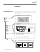
Introduction Manually Change State Chapter 1 RSLogix 5000 programming software has a window that lets you monitor and command an equipment phase. State that the equipment phase is in right now To manually change states. 1. Take ownership of the equipment phase. 2. Give a command. Ownership Ownership locks out programs or FactoryTalk Batch software from giving commands to an equipment phase.
Chapter 1 Introduction Takes ownership My Code Can’t command See the following for additional information. • Equipment Phase Command (PCMD) instruction on page 62. • Equipment Phase Override Command (POVR) instruction on page 68. • Attach to Equipment Phase (PATT) instruction on page 97. Comparison of Other State Models The following table compares PhaseManager software’s state model to other common state models.
Chapter 2 PhaseManager Quick Start Purpose of This Chapter Use this quick start to: • get an introduction to how an equipment phase runs. • monitor an equipment phase. • manually tell an equipment phase to go to a different state. Use this quick start when you want to: • try out PhaseManager software for the first time. • test an equipment phase by manually stepping through its states.
Chapter 2 PhaseManager Quick Start Create an Equipment Phase 1. 2. 3. Create a State Routine 1. 2. 3. 4.
PhaseManager Quick Start Manually Step Through the States Chapter 2 Before you do this procedure, do the following: • Download the project to the controller. • Put the controller in run or remote run mode. Step Notes 1. Right-click the equipment phase and choose Monitor Equipment Phase. 2. Click the ownership button and then Yes—take ownership. Publication LOGIX-UM001B-EN-P - April 2010 This lets you use this window to step through the states.
Chapter 2 PhaseManager Quick Start Step Notes 3. Click Start. • The equipment phase goes to the Running state. • Any code in the Running state routine starts running. This is where you put the code for the normal production sequence of your equipment. 4. Click Stop. • The equipment phase goes to the Stopped state. • The Running state routine stops running. • The Stopping state routine is optional. Without it, the equipment phase goes directly to the Stopped state.
PhaseManager Quick Start Step 5. Click Reset. 6. Click the ownership button. Publication LOGIX-UM001B-EN-P - April 2010 Chapter 2 Notes • The equipment phase goes to the Idle state. • The Resetting state routine is optional. Without it, the equipment phase goes directly to the Idle state. This releases the equipment phase from control by this window.
Chapter 2 PhaseManager Quick Start Configure the Initial State for an Equipment Phase The initial state is the first state to which the equipment phase goes after power up. 1. 2. 3. Choose your initial state. 4.
Chapter 3 Guidelines Purpose of this chapter To guide your development and programming of a Logix5000 project that uses equipment phases Use this chapter: • before you lay-out the equipment phases for your Logix5000 project. • as a reference while you program the project.
Chapter 3 Guidelines Each equipment phase is a specific activity that your equipment does. An equipment phase tells the equipment what to do and when to do it. Equipment Model Guidelines Follow these guidelines to decide how many equipment phases to use. Guideline Details Make sure each equipment phase does an independent activity. Make sure each equipment phase does an activity that is independent (relatively independent) from other equipment.
Guidelines Chapter 3 Example 1: Tank The following example shows the equipment phases for a tank that cooks ingredients. To cook the ingredients, the tank completes these steps. Which become these phases Which commands this equipment 1. Adds water. 2. Heats the water. 3. Adds other ingredients. 4. Mixes all the ingredients. 5. Dispenses the finished product. Example 2: Smart Belt The following example shows a smart belt. The smart belt does only one activity. It spaces product evenly on an exit belt.
Chapter 3 Guidelines State Model Guidelines A state model divides the operating cycle of your equipment into a series of states. Each state is an instant in the operation of the equipment. It's the actions or conditions of the equipment at a given time. Follow these guidelines as you fill out the state model for an equipment phase. Guideline Details Fill out 1 state model for each phase. Each phase runs its own set of states. Fill out 1 state model worksheet for each phase.
Guidelines Chapter 3 Guideline Details Start with the initial state and work through the model. Start with the initial state. Then work forward from that point. Use the following questions to help you. Use only the states that you want.
Chapter 3 Guidelines State Model Worksheet IDLE Start Command Equipment Phase: RUNNING Hold Command HELD HOLDING Done To Done Done Done Hold Command RESTARTING Restart Command RESETTING Stop Command Reset Command STOPPING COMPLETE Done Reset Command STOPPED Abort Command Abort Command ABORTING Done ABORTED Key Waiting State 28 Acting State Publication LOGIX-UM001B-EN-P - April 2010
Guidelines Example 1: Add Water IDLE · No water flow Start Command · Tank Not full · Operator To can Equipment Phase: Add Water RUNNING · Lock equipment in program control Hold Command HOLDING · Stop water HELD · No water flow Done · Operator can control equipment · Unlock equipment from program control · Add water · Unlock equipment from program control control equipment Done Done Done Hold Command RESTARTING · Lock equipment in program control RESETTING Restart Command Stop Command Re
Chapter 3 Guidelines Example 2: Space Parts IDLE · No axes faults Start Command · All axes = on · Exit belt =Tohomed Equipment Phase: Space Parts RUNNING · Jog exit belt Hold Command · Gear other belts HOLDING · Set speed of exit belt = 0 HELD · Speed of exit belt =0 Done · Put 1 box on fine belt · Registration = armed · Put 1 box on each flight Done Done Done Hold Command RESTARTING · Jog exit belt RESETTING · Clear axes faults Restart Command · Turn on all axes · Home exit belt · Arm
Guidelines Equipment Code Guidelines One advantage of an equipment phase is that it lets you separate the procedures (recipes) for how to make the product from the control of the equipment that makes the product. This makes it much easier to execute different procedures for different products using the same equipment.
Chapter 3 Guidelines Example 1: Add Water to a Tank The equipment phase tells the equipment program to go to program mode and add water. The equipment program follows the commands of the equipment phase and sends back its mode and state.
Guidelines Chapter 3 Example 2: Smart Belt The equipment phase tells the equipment program to reset faults. The equipment phase then waits for the equipment program to turn on a done bit. When the done bit turns on, the equipment phase clears the command to reset faults. The equipment phase then goes to the next step in the sequence. The equipment program resets faults when it gets the fault reset command from the equipment phase. It turns on a done bit after it clears the faults.
Chapter 3 Guidelines Execution Guidelines A state model makes it much easier to separate the normal execution of your equipment from any exceptions (faults, failures, off-normal conditions). Use the resetting, running, and stopping states for the normal execution of the equipment. Idle Running Resetting Holding Held Restarting Complete Guideline Use the holding, restarting, and aborting states to handle exceptions (faults, failures, off-normal conditions).
Guidelines Guideline Chapter 3 Details Create a prestate routine just like the routine for a program. It’s not a phase state routine. 1. 2. 3. Choose any language. 4.
Chapter 3 Guidelines Guideline Details Assign a prestate routine. 1. 2. 3. 4. Use a state bit to limit code to a specific state RSLogix 5000 software automatically makes a tag for each equipment phase. The tag has bits that tell you the state of the equipment phase. • The tag is at the controller scope. • The tag uses the PHASE data type. • Use bits of the tag for code that you want to limit to certain states. Example Suppose the name of your equipment phase is My_Phase.
Guidelines Chapter 3 Guideline Details Use the empty phase state routine to complete phase execution Unlike normal program routines, phase state routines are called by the batch manager (not other program routines(, so they always have the potential of being called.
Chapter 3 Guidelines Example 1: Add Water to a Tank The prestate routine watches for equipment faults while the equipment phase is in the running state (Add_Water.Running = 1). If Water_Feed.Health = 1, then a fault happened. If a fault happens, the equipment phase sets a failure code of 202. If Add_Water.Running And Water_Feed.Health Then PFL(202); End_If; The equipment program watches the fault bits of the valve, pump, and their feedback devices.
Guidelines Chapter 3 Example 2: Smart Belt The preset value of this step = 20000 ms. The step turns on its DN bit if it doesn’t clear the faults within 20000 ms. If Step_000.DN = on, a timeout happened. When a timeout happens, the OSR instruction turns on the Clear_Faults_Timeout bit for one scan. If MyPhase is in the resetting state and Clear_Faults_Timeout is on, then the PFL instruction signals a failure. The PFL instruction sets the failure code = 501.
Chapter 3 Guidelines Transition Guidelines To start an acting state, you usually have to give the equipment phase a command. The command tells the equipment phase and its equipment to start doing something or do something different. Use the Equipment Phase Command (PCMD) instruction to give a command to an equipment phase. Optional: You can also use FactoryTalk Batch software in place of a PCMD instruction to trigger transitions Use the state model to see which transitions need a PCMD instruction.
Guidelines Chapter 3 Guideline Details A PCMD instruction causes a transition right away. A PCMD instruction makes an equipment phase go to the commanded state. The equipment phase changes states as soon as it finishes its current scan. This happens even if the current state isn’t done. See if you need to reset the state that you’ve left. Are you leaving an acting state (for example, running, holding)? • YES — Consider resetting the code of the state that you’ve left.
Chapter 3 Guidelines Guideline Details See if you must use a POVR instruction instead of a PCMD instruction. Takes ownership My Code Can’t command A. Are you giving the hold, stop, or abort command? · NO — Use the PCMD instruction. · YES — Go to step B. B. Must the command work even if you have manual control of the equipment phase via RSLogix 5000 software? · YES — Use the POVR instruction instead. See page 68. · NO — Go to step C. C.
Guidelines Chapter 3 Example 1: Tank The controller uses an SFC to command the phases that run the tank (add water, heat, add ingredients, and so forth). Give the start command to the Add_Water equipment phase. The P1 qualifier limits this to the first scan of the step. Wait until the Add_Water equipment phase is done (complete). When the equipment phase is done, give the reset command. The P0 qualifier limits this to the last scan of the step. Start the next equipment phase.
Chapter 3 Guidelines Example 2: Smart Belt If the operator presses the start button on the machine or HMI, then My_Inputs.AnyStartPressed = on for 1 scan. The ONS instruction makes sure that My_Inputs.AnyStartPressed turns on only when a start button goes from off on. If the equipment phase is in the idle state and My_Inputs.AnyStartPressed = on, then The PCMD instruction gives MyPhase the start command.
Guidelines Chapter 3 Example 3: Jam Detection The equipment program watches for the following faults: • Faulted axis • Jammed material If there is a fault, then Local_Interface.Equipment_Faults_Cleared = 0. This tag is an alias for the controller-scoped tag Shear_1. The prestate routine of the equipment phase watches for the equipment program to signal a fault. • If Interface_To_Equipment.Equipment_Faults_Cleared = 0 then there is a fault.
Chapter 3 Guidelines To leave an acting state, you usually signal that the state is done doing what it had to do. Use the Phase State Complete (PSC) instruction to signal when a state is done. State Completion Guidelines IMPORTANT The PSC instruction doesn’t stop the current scan of a routine. When the PSC instruction executes, the controller scans the rest of the routine and then transitions the equipment phase to the next state. The PSC instruction does not terminate the execution of the routine.
Guidelines Chapter 3 Example 1: Add Water to a Tank The holding state does three things. 1. Rung 0 — stop the water. 2. Rung 1 — unlock the devices from program control. 3. Rung 2 — signal that the state is done. Example 2: Smart Belt At the last step of the resetting state: • the SFR instruction resets the SFC so it is ready for the next time you need it. • the PSC instruction signals that the state is done. Note: The P1 qualifier runs the actions only one time.
Chapter 3 Guidelines Equipment Interface Tag Guidelines An equipment interface tag links an equipment phase to an equipment program. • The equipment phase uses the tag to configure and command the equipment program. • The equipment program uses the tag to report its status or condition. You are here.
Guidelines Guideline Details Create a tag for each equipment phase Create tag for the interface data of each equipment phase. Chapter 3 • Make a tag for each equipment phase. • Use the data type from guideline . • Make the tag at the controller scope. Both the equipment phase and the equipment program must get to the tag. • Consider using alias tags. See Alias Tag Guidelines on page 53.
Chapter 3 Guidelines Example 1: Add Water to a Tank 1. The equipment phase and equipment program share this data. Go to program mode Go to this state In program mode No faults Water_Feed LS Hardware OK In this state 2. A user-defined data type creates a template for the data. 3. A tag stores the data that is shared by the equipment phase and equipment program. The tag uses the user-defined data type from step 2.
Guidelines Chapter 3 Example 2: Smart Belt The equipment phase and equipment program share this data. Equipment program interface Commands A separate user-defined data type holds data for each axis.
Chapter 3 Guidelines Example 2: Smart belt, Continued The equipment program gets the command from the equipment phase and passes it to each axis. The equipment program collects the fault status of each axis and passes it back to the equipment phase.
Guidelines Alias Tag Guidelines Chapter 3 Program-scoped tags and phase-scoped tags make your code easier to reuse. Make the tags aliases for tags at the controller scope. If you reuse the equipment phase (for example, copy/paste), simply point the phase-scoped tags to new tags at the controller scope. This reduces address fixes within the code. Example The controller automatically makes a tag for an equipment phase. The tag is at the controller scope (controller tag).
Chapter 3 Guidelines Additional Resources For this information See this publication Guidelines and considerations for alias tags Logix5000 Controllers Design Considerations, publication 1756-RM094 Steps to assign alias tags 54 Logix5000 Controllers Common Procedures Programming Manual, publication 1756-PM001 Publication LOGIX-UM001B-EN-P - April 2010
Appendix A Equipment Phase Instructions (PSC, PCMD, POVR, PFL, PCLF, PXRQ, PRNP, PPD, PATT, PDET) Introduction This appendix provides a description of each equipment phase instruction in this format.
Appendix A Equipment Phase Instructions (PSC, PCMD, POVR, PFL, PCLF, PXRQ, PRNP, PPD, PATT, PDET) Relay Ladder Rung Condition The controller evaluates ladder instructions based on the rung condition preceding the instruction (rung-condition-in). Based on the rung-condition-in and the instruction, the controller sets the rung condition following the instruction (rung-condition-out), which in turn, affects any subsequent instruction.
Equipment Phase Instructions (PSC, PCMD, POVR, PFL, PCLF, PXRQ, PRNP, PPD, PATT, PDET) Prescan of Routines Appendix A The controller also prescans routines. Prescan is a special scan of all routines in the controller. During prescan, the controller: • scans all main routines. • scans all state routines of equipment phases. • scans all prestate routines of equipment phases. • scans all subroutines of programs and equipment phases one time.
Appendix A Equipment Phase Instructions (PSC, PCMD, POVR, PFL, PCLF, PXRQ, PRNP, PPD, PATT, PDET) Choose an Equipment Phase Instruction If You Want To Use This Instruction signal an equipment phase that the state routine is complete so go to the next state Phase State Complete (PSC) Available In These Languages See Page relay ladder 59 structured text change the state or substate of an equipment phase Equipment Phase Command (PCMD) relay ladder 62 structured text give a hold, stop, or abort comm
Equipment Phase Instructions (PSC, PCMD, POVR, PFL, PCLF, PXRQ, PRNP, PPD, PATT, PDET) Phase State Complete (PSC) Appendix A Use the PSC instruction to signal an equipment phase that the state routine is complete so go to the next state. Operands: Relay Ladder none Structured Text none You must enter the parentheses ( ) after the instruction mnemonic, even though there are no operands. Description: The PSC instruction signals the completion of a phase state routine.
Appendix A Equipment Phase Instructions (PSC, PCMD, POVR, PFL, PCLF, PXRQ, PRNP, PPD, PATT, PDET) Guidelines for Using the PSC Instruction Guideline Details Use the PSC instruction in each phase state routine that you add to an equipment phase. Without a PSC instruction, the equipment phase remains in the state and does not go to the next state. • Place the PSC instruction as the last step in your phase state routine. • When the state is done (complete), execute the PSC instruction.
Equipment Phase Instructions (PSC, PCMD, POVR, PFL, PCLF, PXRQ, PRNP, PPD, PATT, PDET) Appendix A Example: Relay Ladder If ThisPhase.StepIndex = 30 (The routine is at step 30.) Then the PSC instruction signals that the state is done (complete). After the controller scans the rest of the routine (rung 5, rung 6, and so forth.), the equipment phase goes to the next Structured Text When the SFC reaches Step_002, the PSC instruction signals that the state is done (complete).
Appendix A Equipment Phase Instructions (PSC, PCMD, POVR, PFL, PCLF, PXRQ, PRNP, PPD, PATT, PDET) Equipment Phase Command (PCMD) Use the PCMD instruction to change the state or substate of an equipment phase.
Equipment Phase Instructions (PSC, PCMD, POVR, PFL, PCLF, PXRQ, PRNP, PPD, PATT, PDET) Appendix A States, Substates, and Commands of an Equipment Phase state command Some states need a command to go to the next state. If the equipment phase is in the idle state, a start command transitions the equipment phase to the running state. Once in the running state, the equipment phase executes its running state routine. Other states use a Phase State Complete (PSC) instruction to go to the next state.
Appendix A Equipment Phase Instructions (PSC, PCMD, POVR, PFL, PCLF, PXRQ, PRNP, PPD, PATT, PDET) Guideline See if you must use a POVR instruction instead of a PCMD instruction. Details A. Are you giving the hold, stop, or abort command? • NO — Use the PCMD instruction. • YES — Go to step B. B. Must the command work even if you have manual control of the equipment phase via RSLogix 5000 software? • YES — Use the POVR instruction instead. See page 68. • NO — Go to step C. C.
Equipment Phase Instructions (PSC, PCMD, POVR, PFL, PCLF, PXRQ, PRNP, PPD, PATT, PDET) Appendix A Code (Dec) Description 24578 The command is not valid for the current state of the equipment phase. For example, if the equipment phase is in the running state, then a start command is not valid. 24579 You cannot command the equipment phase. One of the following already owns the equipment phase.
Appendix A Equipment Phase Instructions (PSC, PCMD, POVR, PFL, PCLF, PXRQ, PRNP, PPD, PATT, PDET) Example 1: Relay Ladder If ProcedureB_StepIndex = 20 (The routine is at step 20.) And this is the transition to step 20 (The ONS instruction signals that the EQU instruction went from false to true.) Then Change the state of the Add_Water equipment phase to running via the start command. If ProcedureB_StepIndex = 20 (The routine is at step 20.) And the Add_Water equipment phase is complete (Add_Water:Phase.
Equipment Phase Instructions (PSC, PCMD, POVR, PFL, PCLF, PXRQ, PRNP, PPD, PATT, PDET) Appendix A Example 2: Relay Ladder If ProcedureB_StepIndex = 30 (The routine is at step 30.) And this is the transition to step 30 (The ONS instruction signals that the EQU instruction went from false to true.) Then Change the Add_Ingredient equipment phase to running via the start command. Verify that the command was successful and store the result code in PCMD_Result[1] (DINT tag).
Appendix A Equipment Phase Instructions (PSC, PCMD, POVR, PFL, PCLF, PXRQ, PRNP, PPD, PATT, PDET) Equipment Phase Override Command (POVR) Use the POVR instruction to give a hold, stop, or abort command to an equipment phase regardless of ownership.
Equipment Phase Instructions (PSC, PCMD, POVR, PFL, PCLF, PXRQ, PRNP, PPD, PATT, PDET) Appendix A Guidelines for Using the POVR Instruction Guideline Details Make sure you want to override other Do you want the equipment to hold, stop, or abort even if you have manual control of the owners. equipment phase via RSLogix 5000 software? • YES — Use the POVR instruction. • NO — Use the PCMD instruction. This also applies to FactoryTalk Batch software or other programs.
Appendix A Equipment Phase Instructions (PSC, PCMD, POVR, PFL, PCLF, PXRQ, PRNP, PPD, PATT, PDET) Execution: Condition Relay Ladder Action Structured Text Action prescan The rung-condition-out is set to false. No action taken. rung-condition-in is false The rung-condition-out is set to false. N/A rung-condition-in is true • The instruction executes. • The rung-condition-out is set to true. N/A scan of structured text N/A In structured text, instructions execute each time they are scanned.
Equipment Phase Instructions (PSC, PCMD, POVR, PFL, PCLF, PXRQ, PRNP, PPD, PATT, PDET) Appendix A Example: The equipment program watches for the following faults: • Faulted axis • Jammed material If there is a fault, then Local_Interface.Equipment_Faults_Cleared = 0. This tag is an alias for the controller-scoped tag Shear_1. The prestate routine of the equipment phase watches for the equipment program to signal a fault. • If Interface_To_Equipment.Equipment_Faults_Cleared = 0 then there is a fault.
Appendix A Equipment Phase Instructions (PSC, PCMD, POVR, PFL, PCLF, PXRQ, PRNP, PPD, PATT, PDET) Equipment Phase Failure (PFL) Use the PFL instruction as an optional method to signal a failure for an equipment phase. Operands: Relay Ladder Operand Type Format Description Failure_Code DINT immediate tag value to which you want to set the failure code for the equipment phase Structured Text The operands are the same as those for the relay ladder PFL instruction.
Equipment Phase Instructions (PSC, PCMD, POVR, PFL, PCLF, PXRQ, PRNP, PPD, PATT, PDET) Appendix A Guidelines for Using the PFL Instruction Guideline Details Put the PFL instruction in the equipment phase. The PFL instruction sets the failure code for the equipment phase in which you put the instruction. There is no operand to identify a specific equipment phase. Typically, put the PFL instruction in a prestate routine for the equipment phase.
Appendix A Equipment Phase Instructions (PSC, PCMD, POVR, PFL, PCLF, PXRQ, PRNP, PPD, PATT, PDET) Guideline Details To clear the failure code, use a PCLF instruction. You must use a PCLF instruction to clear the failure code of an equipment phase. Instructions such as a CLR or MOV won’t change the failure code. See Equipment Phase Clear Failure (PCLF) instruction on page 76.
Equipment Phase Instructions (PSC, PCMD, POVR, PFL, PCLF, PXRQ, PRNP, PPD, PATT, PDET) Appendix A Example: Relay Ladder In the prestate routine of an equipment phase… If Drain_Valve.FaultAlarm = 1 (The valve did not go to the commanded state.) then Failure code for the equipment phase = 102. If Drain_Tank.Running = 1 (The Drain_Tank equipment phase is in the running state.) And Drain_Tank.
Appendix A Equipment Phase Instructions (PSC, PCMD, POVR, PFL, PCLF, PXRQ, PRNP, PPD, PATT, PDET) Equipment Phase Clear Failure (PCLF) Use the PCLF instruction to clear the failure code of an equipment phase. Operands: Relay Ladder Operand Type Format Description Phase Name phase name of the equipment phase Equipment phase whose failure code you want to clear Structured Text The operands are the same as those for the relay ladder PCLF instruction.
Equipment Phase Instructions (PSC, PCMD, POVR, PFL, PCLF, PXRQ, PRNP, PPD, PATT, PDET) Appendix A Execution: Condition Relay Ladder Action Structured Text Action prescan The rung-condition-out is set to false. No action taken. rung-condition-in is false The rung-condition-out is set to false. N/A rung-condition-in is true • The instruction executes. • The rung-condition-out is set to true. N/A scan of structured text N/A In structured text, instructions execute each time they are scanned.
Appendix A Equipment Phase Instructions (PSC, PCMD, POVR, PFL, PCLF, PXRQ, PRNP, PPD, PATT, PDET) Equipment Phase External Request (PXRQ) Use the PXRQ instruction to initiate communication with FactoryTalk Batch software. Operands: Relay Ladder Operand Type Format Description Phase Instruction PHASE_INSTRUCTION tag tag that controls the operation External Request request name type of request For available requests, see page 81.
Equipment Phase Instructions (PSC, PCMD, POVR, PFL, PCLF, PXRQ, PRNP, PPD, PATT, PDET) If You Want To • diagnose the cause of an error • write logic to respond to specific errors use one member for the various status bits of the tag Publication LOGIX-UM001B-EN-P - April 2010 Then Check Or Set This Member Appendix A Data Type Notes ERR INT If ER = 1, the error code gives diagnostic information. To interpret the error code, see ’PXRQ Error Codes’ on page 86.
Appendix A Equipment Phase Instructions (PSC, PCMD, POVR, PFL, PCLF, PXRQ, PRNP, PPD, PATT, PDET) Timing Diagram of a PXRQ Instruction rung-condition-in EN WA IP PC or ER 1 2 3 Description 4 5 6 7 8 Description 1 The rung-condition-in goes true. The instruction sends the request to FactoryTalk Batch software. 5 The rung-condition-in goes true. The instruction sends the request to FactoryTalk Batch software. 2 FactoryTalk Batch software starts processing the request.
Equipment Phase Instructions (PSC, PCMD, POVR, PFL, PCLF, PXRQ, PRNP, PPD, PATT, PDET) Appendix A Guidelines for Using the PXRQ Instruction Guideline Details Make sure to use an array for the Data Values operand. The Data Values operand requires a DINT array, even if the array contains only 1 element (that is, the data type is DINT[1]). In relay ladder, condition the instruction to execute on a transition. This is a transitional instruction.
Appendix A Equipment Phase Instructions (PSC, PCMD, POVR, PFL, PCLF, PXRQ, PRNP, PPD, PATT, PDET) If You Want To Then Configure The PXRQ Instruction As Follows External Request Data Value Value Array Element send a message to an operator Send Message to Operator DINT[0] message ID clear a message from an operator Clear Message to Operator DINT[0] 0 acquire a resource Acquire Resources DINT[0] equipment ID acquire multiple resources Acquire Resources DINT[0] equipment ID DINT[1] equipme
Equipment Phase Instructions (PSC, PCMD, POVR, PFL, PCLF, PXRQ, PRNP, PPD, PATT, PDET) If You Want To Appendix A Then Configure The PXRQ Instruction As Follows External Request Data Value Value Array Element download recipe control verses manual phase control Download Batch Data DINT[0] 4 DINT[1] parameter ID in which to store the value In the result value: 0 = recipe control 1 = manual phase control download current mode of the phase Download Batch Data DINT[0] 5 DINT[1] parameter ID in whi
Appendix A Equipment Phase Instructions (PSC, PCMD, POVR, PFL, PCLF, PXRQ, PRNP, PPD, PATT, PDET) If You Want To Then Configure The PXRQ Instruction As Follows External Request Data Value Value Array Element download information regarding the availability of sufficient material Download Sufficient Material DINT[0] parameter ID in which to store the value In the result value: 0 = insufficient material 1 = sufficient material generate a signature Generate E Signature DINT[0] ID of the signature te
Equipment Phase Instructions (PSC, PCMD, POVR, PFL, PCLF, PXRQ, PRNP, PPD, PATT, PDET) If You Want To upload container attribute upload container priority assignment Appendix A Then Configure The PXRQ Instruction As Follows External Request Data Value Value Array Element Upload Material Track Database Data DINT[0] 8 DINT[1] report ID that has the value DINT[2] controller ID DINT[3] attribute ID DINT[0] 9 DINT[1] report ID that has the value DINT[2] material ID DINT[3] container ID DI
Appendix A Equipment Phase Instructions (PSC, PCMD, POVR, PFL, PCLF, PXRQ, PRNP, PPD, PATT, PDET) PXRQ Error Codes ERR (hex) EXERR (hex) Description Recommended Action 00 0000 The PXRQ instruction was aborted before it sent the request to FactoryTalk Batch software. None 01 0000 The PXRQ instruction was aborted after it sent the request to FactoryTalk Batch software. None 02 0000 2 or more PXRQ instructions executed at the Limit execution to 1 PXRQ instruction at a time.
Equipment Phase Instructions (PSC, PCMD, POVR, PFL, PCLF, PXRQ, PRNP, PPD, PATT, PDET) Appendix A Execution: Condition Relay Ladder Action Structured Text Action prescan The rung-condition-out is set to false. No action taken. rung-condition-in is false The rung-condition-out is set to false. N/A rung-condition-in is true • When the rung-condition-in goes from false to true, the instruction executes one time. • The rung-condition-out is set to true.
Appendix A Equipment Phase Instructions (PSC, PCMD, POVR, PFL, PCLF, PXRQ, PRNP, PPD, PATT, PDET) Example: Relay Ladder If ThisPhase.StepIndex.1 = 1 (The routine is at step 1.), then Send the Acquire Resources request to FactoryTalk Batch software. The DataValues tag is a DINT array that contains the equipment IDs of the resources. When RQ_Control[0].PC = 1 or RQ_Control[0].ER = 1 (The request is complete or it failed.), then Done = 1. (This signals the sequence to go to the next step.
Equipment Phase Instructions (PSC, PCMD, POVR, PFL, PCLF, PXRQ, PRNP, PPD, PATT, PDET) Equipment Phase New Parameters (PRNP) Appendix A Use the PRNP instruction to clear the NewInputParameters bit of an equipment phase. Operands: Relay Ladder none Structured Text none You must enter the parentheses ( ) after the instruction mnemonic, even though there are no operands. Description: The PRNP instruction clears the NewInputParameters bit of the equipment phase.
Appendix A Equipment Phase Instructions (PSC, PCMD, POVR, PFL, PCLF, PXRQ, PRNP, PPD, PATT, PDET) Execution: Condition Relay Ladder Action Structured Text Action prescan The rung-condition-out is set to false. No action taken. rung-condition-in is false The rung-condition-out is set to false. N/A rung-condition-in is true • The instruction executes. • The rung-condition-out is set to true. N/A scan of structured text N/A In structured text, instructions execute each time they are scanned.
Equipment Phase Instructions (PSC, PCMD, POVR, PFL, PCLF, PXRQ, PRNP, PPD, PATT, PDET) Appendix A Structured Text This is a stored action. It continues to execute even after the SFC leaves Step_001. If ThisPhase.NewInputParameters = 1 (FactoryTalk Batch software has new input parameters for the equipment phase), then If Enable_PXRQ = 1 (Let the PXRQ instruction execute.) Or RQ_Control[0]. PC = 0 (The PXRQ instruction is in process.), then DataValues[0] = 2.
Appendix A Equipment Phase Instructions (PSC, PCMD, POVR, PFL, PCLF, PXRQ, PRNP, PPD, PATT, PDET) Equipment Phase Paused (PPD) Use the PPD instruction to set up breakpoints within the logic of an equipment phase. Operands: Relay Ladder none Structured Text none You must enter the parentheses ( ) after the instruction mnemonic, even though there are no operands. Description: The PPD instruction lets you stop execution at a specific step (breakpoint) to test and troubleshoot your logic.
Equipment Phase Instructions (PSC, PCMD, POVR, PFL, PCLF, PXRQ, PRNP, PPD, PATT, PDET) Appendix A The following timing diagram shows how the PPD instruction effects the substate bits of a PHASE tag. phase_name.AutoPause phase_name.Pausing phase_name.Paused phase_name.Running rung-condition-in rung-condition-out 1 2 3 4 Description Publication LOGIX-UM001B-EN-P - April 2010 1 The equipment phase gets the auto pause command. 2 The equipment phase gets the start command.
Appendix A Equipment Phase Instructions (PSC, PCMD, POVR, PFL, PCLF, PXRQ, PRNP, PPD, PATT, PDET) Guidelines for Using Breakpoints Guideline Details Organize your logic as a series of steps. PPD instructions (breakpoints) are easiest to use if your logic moves through defined steps, such as a state machine or SFC. • A breakpoint only signals that specific conditions are met. It does not stop the execution of the equipment phase.
Equipment Phase Instructions (PSC, PCMD, POVR, PFL, PCLF, PXRQ, PRNP, PPD, PATT, PDET) Appendix A Execution: Condition Relay Ladder Action Structured Text Action Prescan The rung-condition-out is set to false. No action taken. Rung-condition-in is false The rung-condition-out is set to false. N/A Rung-condition-in is true The instruction executes. N/A Scan of structured text N/A In structured text, instructions execute each time they are scanned.
Appendix A Equipment Phase Instructions (PSC, PCMD, POVR, PFL, PCLF, PXRQ, PRNP, PPD, PATT, PDET) Example: Relay Ladder If the equipment phase is in the pausing substate And ThisPhase.StepIndex = 20 (The routine is at step 20.) And FillTime.DN = On Then the PPD instruction prevents the MOV instruction from moving the routine to step 30 until the equipment phase gets the resume command. (The routine stays at step 20.
Equipment Phase Instructions (PSC, PCMD, POVR, PFL, PCLF, PXRQ, PRNP, PPD, PATT, PDET) Attach to Equipment Phase (PATT) Appendix A Use the PATT instruction to take ownership of an equipment phase to either: • prevent another program or FactoryTalk Batch software from commanding an equipment phase. • make sure another program or FactoryTalk Batch software does not already own an equipment phase.
Appendix A Equipment Phase Instructions (PSC, PCMD, POVR, PFL, PCLF, PXRQ, PRNP, PPD, PATT, PDET) Guidelines for Using the PATT Instruction Guideline Consider ownership if you have multiple sequencers that use a common equipment phase. Details Ownership makes sure that a program can command all the equipment phases it needs and locks out any other sequencers.
Equipment Phase Instructions (PSC, PCMD, POVR, PFL, PCLF, PXRQ, PRNP, PPD, PATT, PDET) Appendix A PATT Result Codes If you assign a tag to store the result of a PATT instruction, the instruction returns one of the following codes when it executes. Code (Dec) Description 0 The command was successful. 24579 RSLogix 5000 software already owns the equipment phase. • This program now also owns the equipment phase.
Appendix A Equipment Phase Instructions (PSC, PCMD, POVR, PFL, PCLF, PXRQ, PRNP, PPD, PATT, PDET) Example: Relay Ladder If Step.1 = 1 (first step in the sequence) then Each PATT instruction tries to take ownership of an equipment phase. If the Result of a PATT instruction = 0 or 24582 (the program owns the equipment phase), then A bit within the Ownership tag = 1. (In the Ownership tag, each equipment phase is assigned a bit.
Equipment Phase Instructions (PSC, PCMD, POVR, PFL, PCLF, PXRQ, PRNP, PPD, PATT, PDET) Appendix A Structured Text At the first step in the sequence, this action tries to take ownership of 2 equipment phases that the sequence uses. This action checks that the program owns the equipment phases. If the Result of each PATT instruction = 0 or 24582 (the program owns the equipment phase), then A bit within the Ownership tag = 1. (In the Ownership tag, each equipment phase is assigned a bit.
Appendix A Equipment Phase Instructions (PSC, PCMD, POVR, PFL, PCLF, PXRQ, PRNP, PPD, PATT, PDET) Detach from Equipment Phase (PDET) Use the PDET instruction to relinquish ownership of an equipment phase. Operands: Relay Ladder Operand Type Phase Name phase Format Description name of the equipment phase Equipment phase that you no longer want to own Structured Text The operands are the same as those for the relay ladder PDET instruction.
Equipment Phase Instructions (PSC, PCMD, POVR, PFL, PCLF, PXRQ, PRNP, PPD, PATT, PDET) Appendix A Example: Relay Ladder If Step.6 = 1 (step 6 in the sequence) then Each PDET instruction relinquishes ownership of the equipment phases that the sequence owned. Each Ownership bit = 0. (In the Ownership tag, each equipment phase is assigned a bit.) Done = 1. (This signals the sequence to go to the next step.
Appendix A 104 Equipment Phase Instructions (PSC, PCMD, POVR, PFL, PCLF, PXRQ, PRNP, PPD, PATT, PDET) Publication LOGIX-UM001B-EN-P - April 2010
Appendix B PHASE Data Type The PHASE data type gives you status information about an equipment phase. Introduction When you create an equipment phase, RSLogix 5000 software creates a tag for the status of the equipment phase. controller scope name = phase_name PHASE data type Set and Clear Equipment Phase Tag Values For most of the members of the PHASE data type, you can only monitor its value. You can control only the following members.
Appendix B PHASE Data Type Member Control Method NewInputParameters To clear the NewInputParameters bit, use an Equipment Phase New Parameters (PRNP) instruction. Producing Use bit-level instructions or an assignment to set or clear this bit (for example, OTE, :=). Standby Use bit-level instructions or an assignment to set or clear this bit (for example, OTE, :=).
PHASE Data Type If you want to Then check this member Data type Notes see if the equipment phase is in the stopped state Stopped BOOL Read–only see if the equipment phase is in the aborted state Aborted BOOL Read–only use one member to monitor the substate of an equipment phase Substate DINT Read–only For this substate Use this bit Pausing 0 Paused 1 AutoPause 2 see if the equipment phase is in the pausing substate Pausing BOOL Read–only see if the equipment phase is in the pause
Appendix B PHASE Data Type If you want to Then check this member Data type Notes see if a Release Resources request is in process via a PXRQ instruction ReleaseResources BOOL Read–only see if a Send Message To Linked Phase request is in process via a PXRQ instruction SendMessageToLinked Phase BOOL Read–only see if a Send Message To Linked Phase And Wait request is in process via a PXRQ instruction SendMessageToLinked PhaseAndWait BOOL Read–only see if a Receive Message From Linked Phase re
PHASE Data Type Appendix B If you want to Then check this member Data type Notes initiate a producing state Producing BOOL Logix5000 equipment phases don’t have a producing state. To create a producing state, use the Producing bit. initiate a standby state Standby BOOL Logix5000 equipment phases don’t have a standby state. To create a standby state, use the Standby bit.
Appendix B PHASE Data Type Notes: 108 Publication LOGIX-UM001B-EN-P - April 2010
Appendix C Configure an Equipment Phase This appendix steps you through the configuration settings for an equipment phase. Introduction Use this appendix when you want to change the default settings of an equipment phase. Open the Configuration for an Equipment Phase 1. 2.
Appendix C Configure an Equipment Phase Equipment Phase Settings Setting Use the following settings to configure an equipment phase. Choices Prestate prestate routine current state routine The prestate routine runs all the time, even when the equipment phase is in the idle state. It runs before each scan of a state. Do you want to run a prestate routine? YES — Select the routine that you want to run. NO — Leave this box set to none.
Configure an Equipment Phase Setting External Sequencer Loss of Communication Command Appendix C Choices A. Are you using RSBizWare Batch software to command this equipment phase? NO — Skip this box. YES — Go to step B. B. If the controller loses communication with RSBizWare Batch software, what do you want the equipment phase to do? Continue in its current state — Choose None. Go to aborting — Choose Abort. Go to holding — Choose Hold. Go to stopping — Choose Stop.
Appendix C Configure an Equipment Phase Notes: 112 Publication LOGIX-UM001B-EN-P - April 2010
Glossary This manual uses the following terms: Term Definition Example Unit A group of equipment that works together to produce the product or interim product. The equipment of a unit operates independent (relatively independent) from other equipment. brew kettle mixing tank bottle filling machine bottle capping machine Equipment module A group of input devices, output devices, motors, drives, and soft controls (PID loops, totalizers, and so forth.
Glossary Notes: 114 Publication LOGIX-UM001B-EN-P - April 2010
Index A aborted state use 13 aborting state use 13, 34 add equipment phase 18 phase state routine 18 attach to equipment phase instruction 96 B breakpoint See PPD instruction C clear PHASE tag values 103 command example 43, 44 give 14, 62 give with PCMD instruction 40 give with RSLogix 5000 software 19 complete state use 13 configure equipment phase 109 create equipment phase 18 phase state routine 18 D detach from equipment phase instruction 101 E equipment module See equipment program equipment phase
Index equipment program interface tag 48 lay out the code 31 set up the data 48 use 31 example 89 clear a failure code 76 equipment phases for a machine 25 equpment phases for a tank 25 get a result code 66 give a command 65 handle a fault 74 handle a jam 45, 70 handle fault of a device 38 handle timeout 39 interface tag for a machine 51 interface tags for a tank 50 let go of ownership 102 machine is done resetting 47 override an owner 70 procedure for a tank 43 separate code for a machine 33 separate code
Index prestate routine add 35 assign 36 example 38, 39, 44, 45 overview 34 use 34 PRNP instruction 88 producing state set up 26 program equipment phase 31 PSC instruction 59 PXRQ instruction 77 hold action 111 lost communication 111 R report send 77 resetting state use 13 restarting state use 13, 34 routine add phase state routine 18 RSBizWare Batch software external request 77 report 77 RSLogix 5000 software give command 19 monitor an equipment phase 15, 19 ownership 15 running state use 13 S sequencer
Index Notes: 118 Publication LOGIX-UM001B-EN-P - April 2010
Rockwell Automation Support Rockwell Automation provides technical information on the Web to assist you in using its products. At http://www.rockwellautomation.com/support/, you can find technical manuals, a knowledge base of FAQs, technical and application notes, sample code and links to software service packs, and a MySupport feature that you can customize to make the best use of these tools.